
VideoGODIAG GT100 OBD2 Breakout Box & ECU Bench Connector
1 / 4
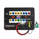
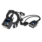
GODIAG GT100 OBD2 Breakout Box & ECU Bench Connector
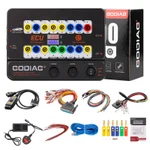
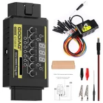
GODIAG GT100 is a 16-pin OBD2 breakout box for communication checks and supported ECU bench connections. It provides voltage monitoring, protocol activity indicators and jumper-wire access for use with compatible diagnostic or programming equipment. Reading, writing, cloning and key-programming functions depend on the connected tool, software and specific module.
€73€79
Quantity
Delivery & shipping options
- Standard delivery
- Free
- Dispatch from
- EU
- Total incl. shipping:
- €73
- Estimated delivery
- 8–15 Working Days
- Returns
- 30 days from delivery
Frequently Bought Together
Full Kit-GT100+ BMW PLatform
GT100 Kit
Overview
Overview
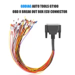
The GT100 separates the vehicle OBD2 interface into individual test connections for signal detection, electrical-level conversion, and module work. Protocol LEDs indicate communication activity, while the display shows voltage. Its banana sockets and DB25 jumper connection support single/multiple ECU setups, OBD1-to-OBD2 connection arrangements, and the listed IMMO wake-up procedures. Key programming requires the relevant connected programmer and test platform.
Specifications
| Diagnostic Port | OBDII |
|---|---|
| Working Voltage | DC 9V-24V |
| Working Power | 0.5-0.6W |
| Adapter Power | Input AC 100V-240V / Output DC 12V 1A |
|---|---|
| Operating Temperature Range | -20°C to 70°C (-4°F to 158°F) |
| Storage Temperature Range | -40°C to 85°C (-40°F to 185°F) |
Package list
| Item | Qty |
|---|---|
| Host | 1 |
| OBD 2-in-1 extension cable | 1 |
| Colored jumper wire set | 1 |
| 12V power supply | 1 |
| Item | Qty |
|---|---|
| 120Ω resistor | 1 |
| Banana plugs | 6 |
| Dupont 2.54mm female pin connectors (wire accessories) | 24 |
Description
Description
GODIAG GT100 OBDII Protocol Detector & OBD2 Breakout Box ECU Connector
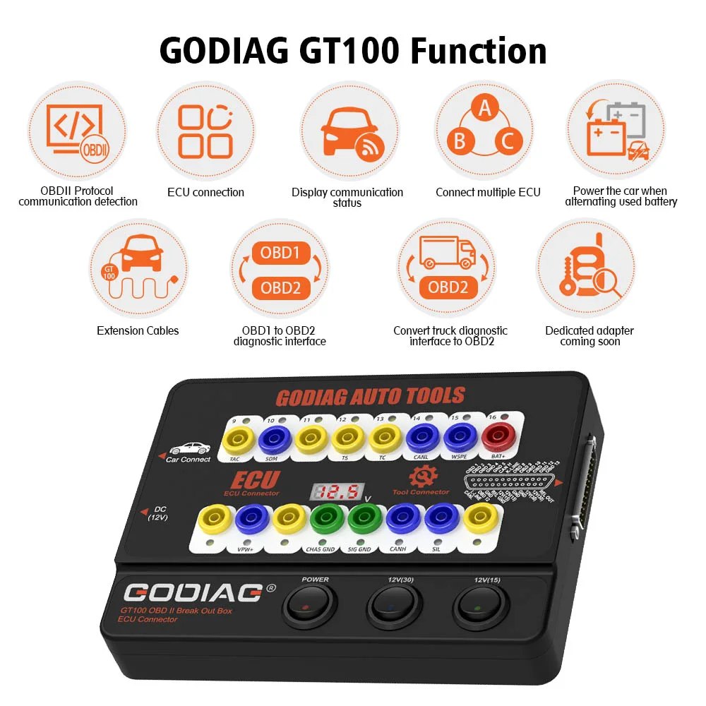
GODIAG GT100 converts the vehicle OBD2 interface into 16 individual test connections for signal detection and electrical-level conversion. It supports communication checks and single- or multiple-module connections for ECU maintenance, diagnosis, programming, and coding with connected diagnostic equipment.
It can also provide an auxiliary power connection during battery replacement to help retain module data and reduce power-loss-related lockouts, remote-key failures, audio lockout, and warning-light activation.
Note: The GT100 displays voltage. Current display is an added feature of the GT100+; the standard GT100 does not provide a current readout.
Diagnostic Tool & Key-Programming Applications
The supplied description lists Xhorse VVDI2, Autel scanners, Launch scanners, and Vident scanners among compatible diagnostic equipment.
Instrument / IMMO Wake-Up for Supported All-Keys-Lost Procedures
- Porsche / VAG applications: the supplied procedure connects banana pin 16 to pin 1 to power or wake the instrument / IMMO system before data collection with a key programmer. Listed examples include A6L, Touareg, A4, Q5, and A7. On some vehicles, including the listed A6L / Q7 examples, data may be collected even when the instrument panel does not illuminate.
- Toyota: supports the described engine-ECU replacement / matching workflow and the listed all-keys-lost procedure using pins 13 and 4 together with a key programmer.
- Mitsubishi: the supplied all-keys-lost key / remote-matching procedure uses OBDII pins 1 and 4.
BMW Test-Platform Applications
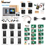
Used with the corresponding BMW CAS4/CAS4+Programming Test Platform or BMW FEM/BDC Programming Test Platform and a compatible tool such as Xhorse VVDI2, Lonsdor K518, CGDI, or Autel IM608, GT100 provides the described off-site key-programming, all-keys-lost, and add-key connections.
Note: These applications require the relevant vehicle-specific procedure, key programmer, and test platform where specified. The BMW platforms are supporting equipment, not an included-item claim for this GT100 listing.
Communication & Voltage Monitoring
Connect the vehicle and diagnostic tool through GT100 to monitor OBDII communication using the protocol LEDs. The display shows the vehicle OBDII interface voltage in real time.
Note: If the displayed voltage is below 11 V, stop diagnosis and programming as instructed in the supplied material to reduce the risk of starting problems, data loss, or module lockout.
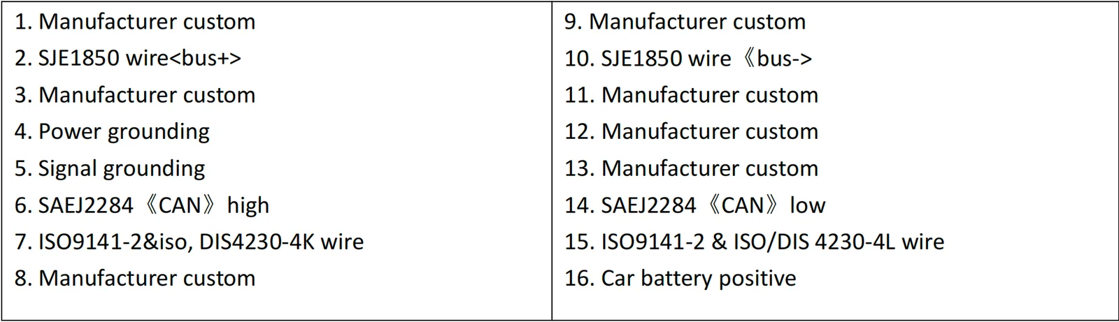
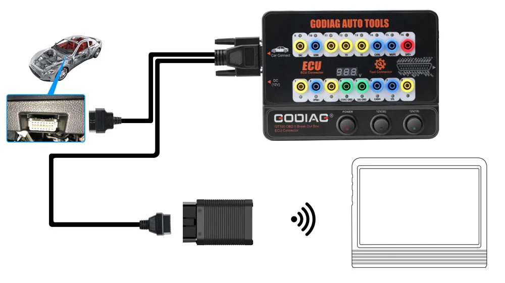
1. OBDII Protocol & Communication Detection
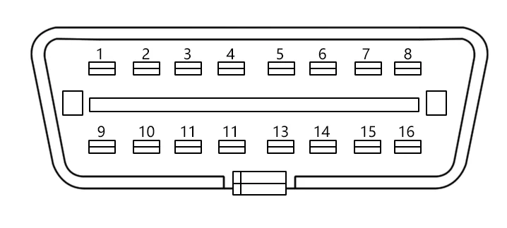
- Connect GT100 to the vehicle OBDII diagnostic port.
- Once the voltage is displayed, turn ON the GT100 power switch.
- Connect the diagnostic tool. During communication, the corresponding protocol LED lights or flashes. The supplied CAN description notes maximum brightness on detection, followed by dimming or faint flashing of CAN-H and CAN-L when communication is established.
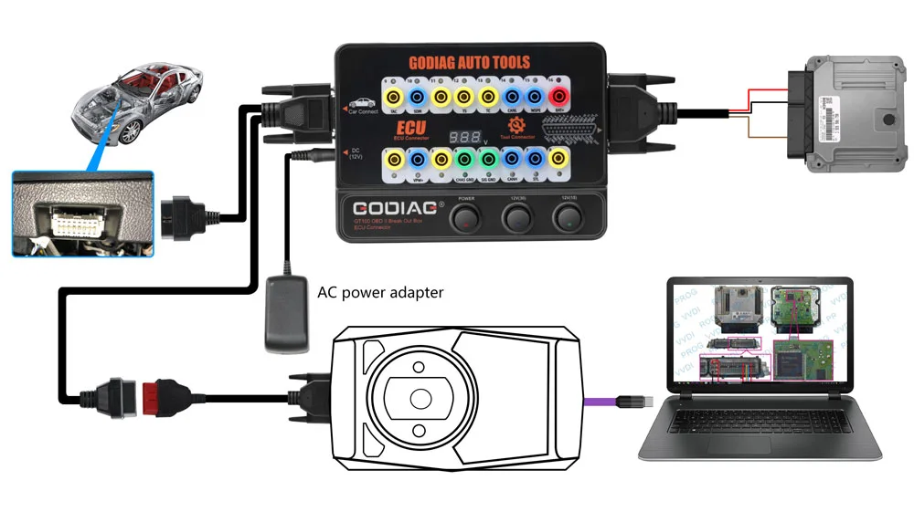
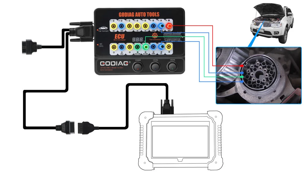
2. Single ECU Module Connection
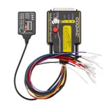
- Connect the ECU with the colored jumper wires. For a CAN ECU, check whether a 120 Ω terminating resistor is required.
- Power GT100 through the vehicle OBDII diagnostic interface or an AC power adapter.
- Connect the diagnostic tool or ECU programmer to perform the supported single-module operation.
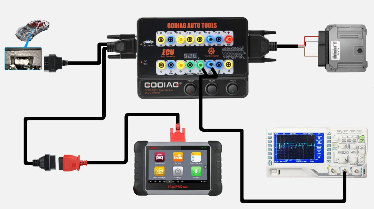
3. Banana Plug Extension Connection
Extends the vehicle OBDII 16-pin interface for connection checks and OBDII interface voltage-waveform testing.
4. OBD1-to-OBD2 Diagnostic Interface Conversion
Use the appropriate connector to convert the OBD1 diagnostic interface to standard OBD2 connections according to the vehicle diagnostic communication protocol.
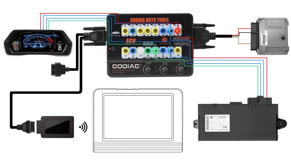
5. Multiple ECU Module Connection
Connect multiple ECU control modules simultaneously for system-level diagnosis and maintenance.
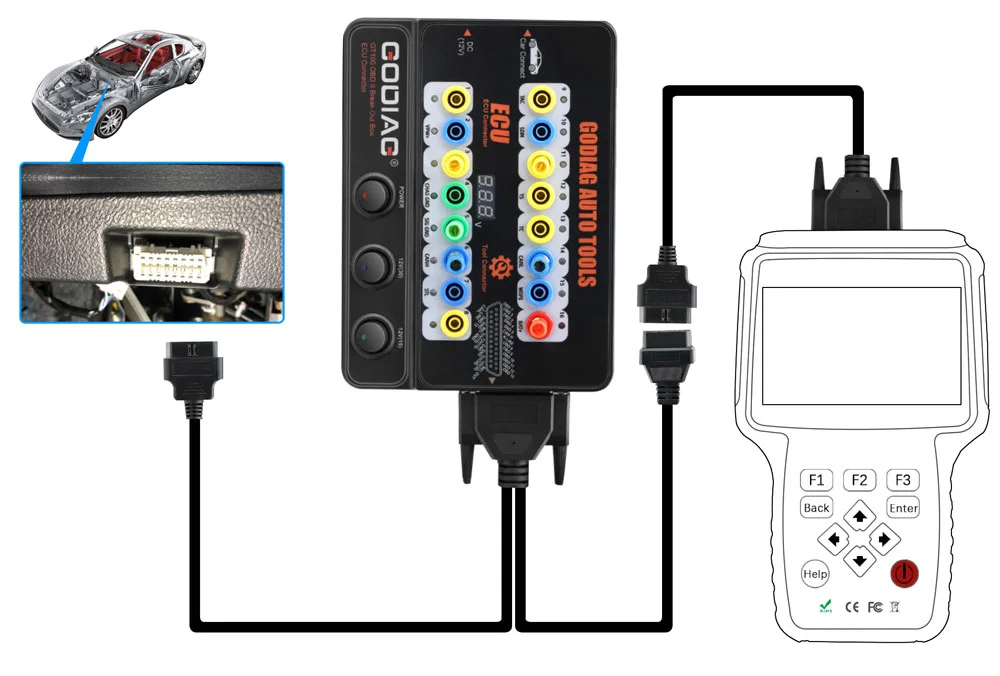
6. Diagnostic Cable Extension
Provides a 1.2 m extension when the diagnostic port is difficult to access or the diagnostic cable is too short.
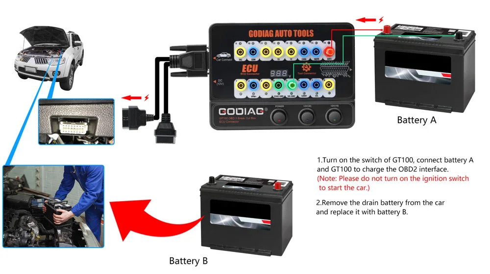
7. Auxiliary Power During Battery Replacement
Connect auxiliary Battery A to GT100 pins 16, 4, and 5 and connect GT100 to the vehicle OBD2 diagnostic interface.
Notice: Turn ON the GT100 power switch. Do NOT turn ON the vehicle ignition switch or start the vehicle during this procedure.
Replace the old vehicle battery with new Battery B while maintaining the auxiliary supply. This helps preserve module data and avoid power-loss-related audio lockout or module malfunction.
Hardware Connection Diagrams
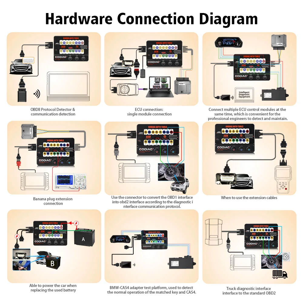
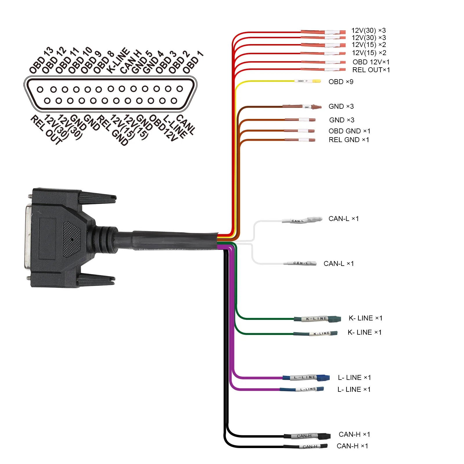
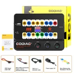
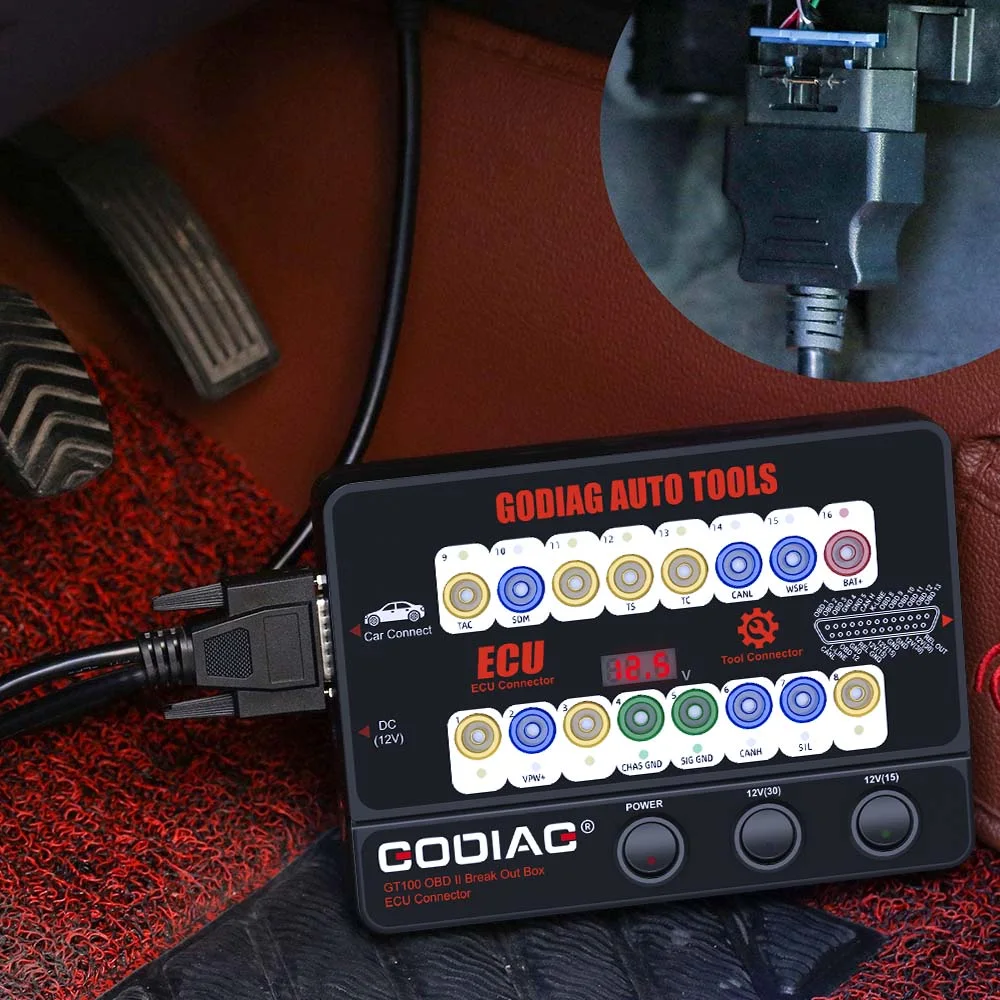
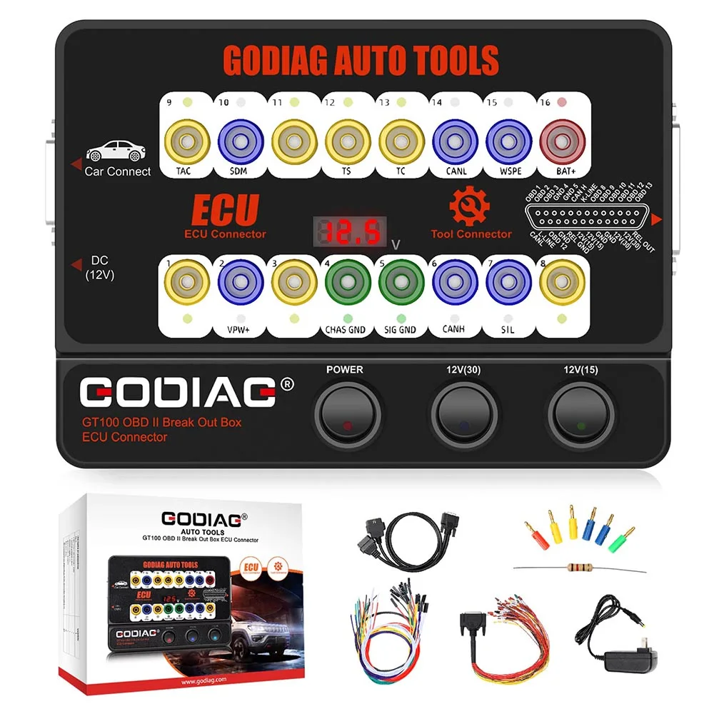
Each OBDII pin has a 4 mm safety banana socket and a colored status LED. Test leads and probes with 4 mm banana plugs connect directly to these sockets.
- Green on pins 4 / 5: ground.
- Red on pin 16: power.
- Flashing blue: communication lines.
The front panel has three switches: the master power switch and two separate 12 V outputs for powering modules through the DB25 jumper cable.
Warranty & Dispatch
The supplied offer specifies a one-year warranty and EU / UK dispatch options with tax-inclusive pricing.
Specifications
Specifications
| Parameter | Details |
|---|---|
| Diagnostic Port | OBDII |
| Working Voltage | DC 9V-24V |
| Working Power | 0.5-0.6W |
| Adapter Power | Input AC 100V-240V / Output DC 12V 1A |
| Operating Temperature Range | -20°C to 70°C (-4°F to 158°F) |
| Storage Temperature Range | -40°C to 85°C (-40°F to 185°F) |
Downloads
Product FAQ
Ask a questionCan I connect an OBD2 scanner to an ECU on the bench using the GODIAG GT100?
Yes, for supported modules and diagnostic tools. The GODIAG GT100 provides breakout connections so you can connect an OBD2 scanner to an ECU on the bench using the correct module pinout and power supply. You still need a compatible scanner or programmer and the appropriate software. GT100 does not independently read fault codes, program modules or clone ECU data.
Why does my ECU power up but not communicate through the GT100?
For ECU bench testing with no communication, check the module-specific wiring diagram, power and ground connections, ignition or wake-up requirements, communication protocol and diagnostic-tool support. Some modules also require other network components. A power indicator or voltage reading confirms only part of the setup; it does not prove that the ECU is awake or ready to communicate.
Do I always need a 120-ohm resistor for CAN bus bench testing?
No. Whether you need an additional 120-ohm resistor for CAN bus bench testing depends on the existing termination in the ECU, interface and bench harness. Follow the wiring requirements for the specific setup. Do not add a resistor automatically if the network is already correctly terminated. CAN termination requirements do not apply to a K-Line-only connection.
Can the GT100 bench-test a used ECU before I install it?
The GT100 can support connections used to bench test a used ECU before installation, provided your diagnostic tool supports the module. You may be able to check identification, communication and supported diagnostic information. However, a successful connection is not a complete functional test. Testing sensor inputs, actuator outputs and operation under load may require additional equipment or in-vehicle testing.
Can I use the GT100 for ECU cloning without opening the ECU?
The GT100 alone cannot provide ECU cloning without opening the ECU. Whether a non-opening bench procedure is available depends on the exact ECU hardware, software version, security requirements and programmer support. Confirm the supported procedure with your programming-tool documentation before purchase. A successful connection does not guarantee that the tool can obtain or write all data required for cloning.
Can I perform bench diagnostics without a gateway module?
Some modules support direct connections, while others depend on a gateway, wake-up messages or additional control units. Bench diagnostics without a gateway module therefore depends on the specific vehicle network and ECU. GT100 provides connection access; it does not automatically emulate missing network components. Send us the module part number and your diagnostic-tool model so we can check the documented requirements.
Customer reviews
Highest rated firstIt is ok