
VideoGODIAG GT100 OBDII Protocol Detector with BMW FEM/BDC Test Platform Support All Key Lost
1 / 8
GODIAG GT100 OBDII Protocol Detector with BMW FEM/BDC Test Platform Support All Key Lost
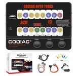
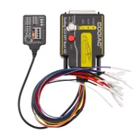
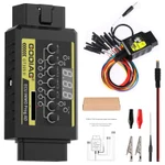
GODIAG GT100 OBDII Breakout Box bundled with the BMW FEM/BDC Test Platform for OBDII communication checks, ECU connections and supported FEM/BDC bench key-synchronization workflows with compatible external equipment.
€107€119
Quantity
Delivery & shipping options
- Standard delivery
- Free
- Dispatch from
- EU
- Total incl. shipping:
- €107
- Estimated delivery
- 8–15 Working Days
- Returns
- 30 days from delivery
Frequently Bought Together
Overview
Overview
The GT100 provides 16-pin OBDII breakout access, voltage display, protocol LED indication and connections for single- or multiple-ECU work. The BMW FEM/BDC platform adds bench module connections, programmed-key synchronization checks and troubleshooting support. Compatible external programming equipment is required for applicable add-key, all-keys-lost, data-backup and module-replacement procedures.
Specifications
| GT100 diagnostic port | OBDII; 16-pin breakout access |
|---|---|
| GT100 working voltage | DC 9–24V |
| GT100 power consumption | 0.5–0.6W |
| GT100 power adapter input | AC 100–240V |
| GT100 power adapter output | DC 12V / 1A |
|---|---|
| GT100 operating temperature | −20°C to 70°C (−4°F to 158°F) |
| GT100 storage temperature | −40°C to 85°C (−40°F to 185°F) |
| Diagnostic extension length | 1.2 m |
Showing 8 of 15 specifications
Package list
| Item | Qty |
|---|---|
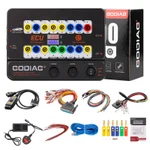
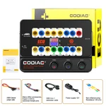
| Host | 1 |
| OBD 2-in-1 extension cable | 1 |
| Colored jumper cable | 1 |
| Power supply 12V | 1 |
| Resistance 120 ohm | 1 |
| Item | Qty |
|---|---|
| Banana plug | 6 |
| Wire accessories Dupont 2.54mm connector female pin | 24 |
| BMW FEM BDC Programming Test Platform | 1 |
| GODIAG OBD2 to OBD25 | 1 |
Description
Description
GODIAG GT100 OBDII Breakout Box with BMW FEM/BDC Test Platform
This bundle combines the GODIAG GT100 OBDII Breakout Box and BMW FEM/BDC Programming Test Platform for connection checks and supported bench work using compatible external diagnostic or programming equipment.
GODIAG GT100 Voltage and Communication Checks
Connect GT100 between the vehicle OBDII port and a compatible diagnostic tool. The display shows vehicle OBDII voltage, while LEDs indicate activity on the corresponding communication lines.
Note: Stop diagnosis or programming if the displayed vehicle voltage is below 11V, as stated in the GT100 operating guide.
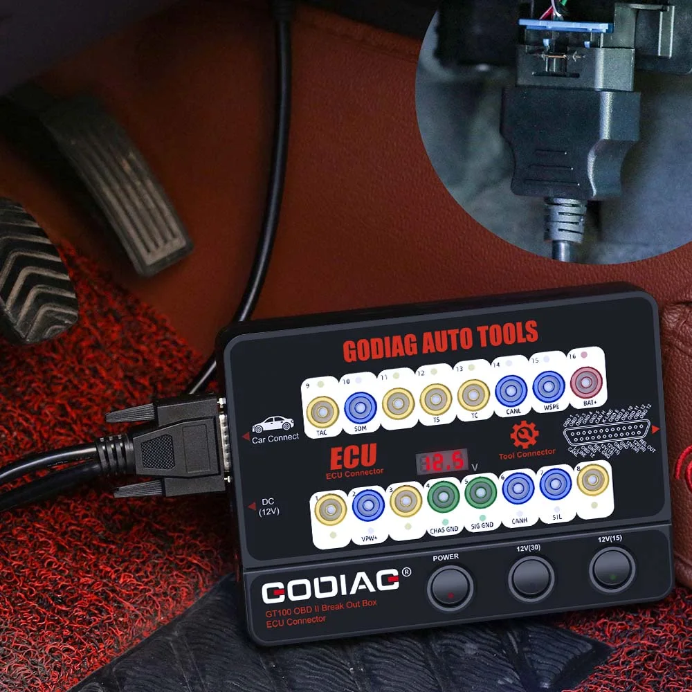
OBDII 16-Pin Reference
- Pin 1 — manufacturer-specific.
- Pin 2 — SAE J1850 Bus +.
- Pin 3 — manufacturer-specific.
- Pin 4 — chassis/power ground.
- Pin 5 — signal ground.
- Pin 6 — CAN High.
- Pin 7 — K-Line.
- Pin 8 — manufacturer-specific.
- Pin 9 — manufacturer-specific.
- Pin 10 — SAE J1850 Bus −, where applicable.
- Pin 11 — manufacturer-specific.
- Pin 12 — manufacturer-specific.
- Pin 13 — manufacturer-specific.
- Pin 14 — CAN Low.
- Pin 15 — L-Line.
- Pin 16 — vehicle battery positive.
Note: Use the wiring and protocol for the exact vehicle or module. Not every vehicle uses every pin.
1. OBDII Protocol Detector & Communication Detection
- Connect GT100 to the vehicle OBDII diagnostic port.
- When voltage is displayed, turn on the GT100 power switch.
- Connect the diagnostic tool and observe the relevant protocol LEDs during communication.
The guide describes bright CAN indication during detection, followed by dim or weakly flashing CAN-H/CAN-L indication during successful communication.
2. ECU Connection — Single Module
Connect a single ECU for supported diagnosis or programming with compatible equipment.
- Connect the ECU using the colored jumpers. For a CAN ECU, check whether the selected setup requires a 120Ω resistor.
- Power GT100 through the vehicle OBDII connection or the appropriate AC power adapter.
- Connect the diagnostic tool or ECU programmer for the supported single-module procedure.
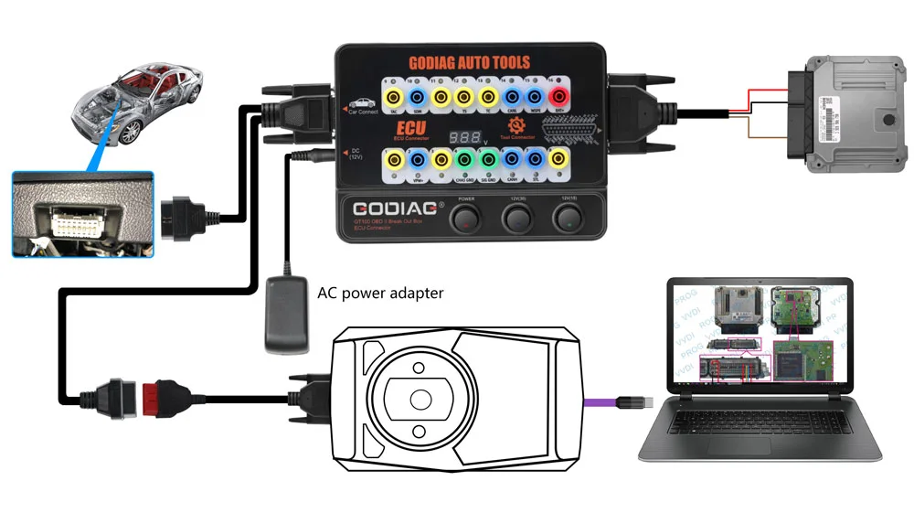
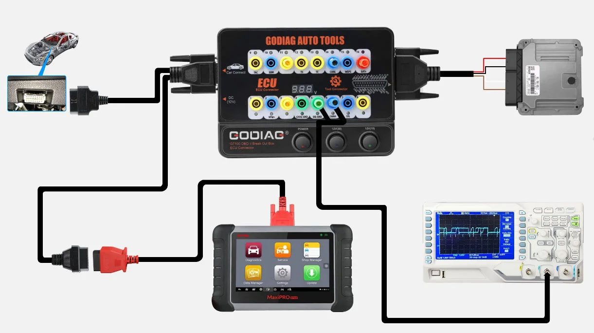
3. Banana Plug Extension Connection
Extend access to the OBDII 16-pin interface through the banana connections for connection checks and voltage waveform testing with suitable external test equipment.
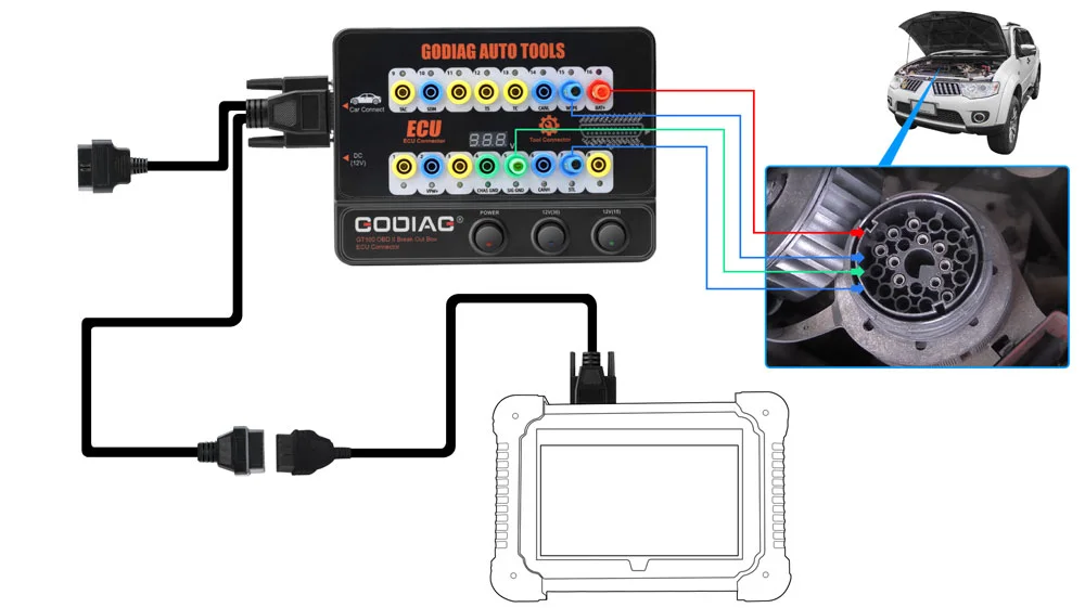
4. OBD1 to OBD2 Connection Adaptation
Use the appropriate connector to adapt an OBD1 or manufacturer-specific connection to an OBD2 tool connection according to the matching communication protocol.
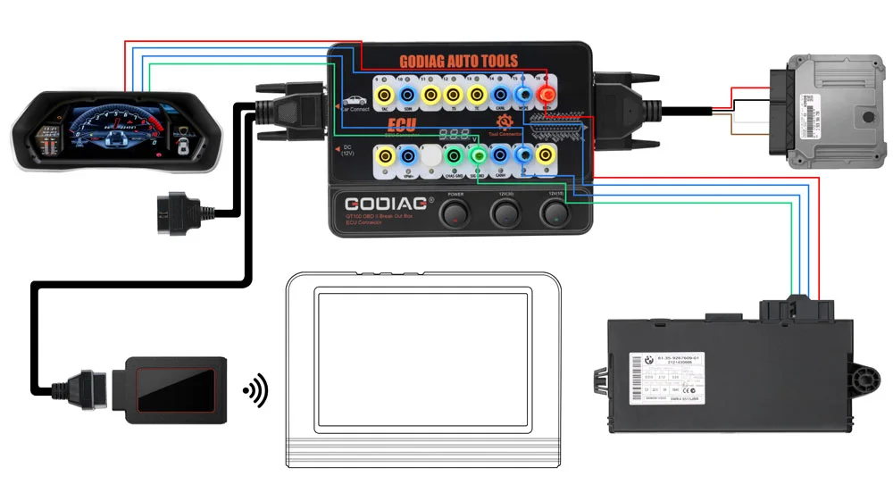
5. Multiple ECU Module Connections
Connect multiple ECU control modules when required for the supported diagnostic, maintenance, or programming workflow.
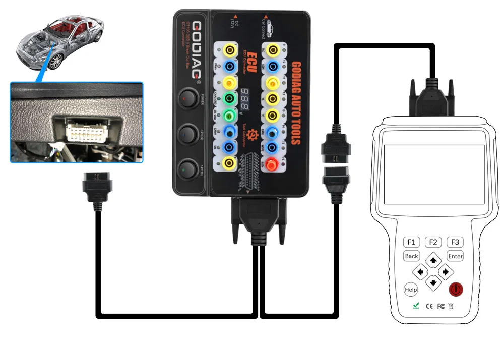
6. Diagnostic Extension Cable
Use the 1.2 m diagnostic extension when the vehicle port is difficult to access or the existing tool cable is too short.
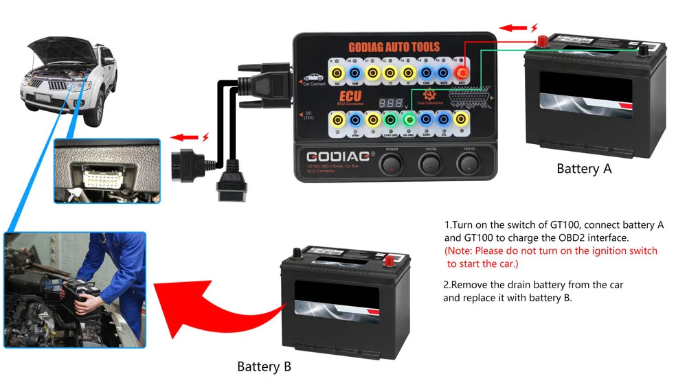
7. Auxiliary Power During Battery Replacement
Provide an auxiliary vehicle power connection during a supported battery-service procedure using the appropriate external battery or power adapter.
- Connect the auxiliary battery supply through GT100 positions 16 / 4 / 5 and connect GT100 to the vehicle OBDII interface.
- Turn on GT100 power.
- Maintain auxiliary power while replacing the old vehicle battery with the new battery.
Note: Do not turn on the ignition or start the vehicle during this auxiliary battery-replacement procedure. Follow the appropriate vehicle procedure and use a suitable power source.
GT100 Hardware and DB25 Connections
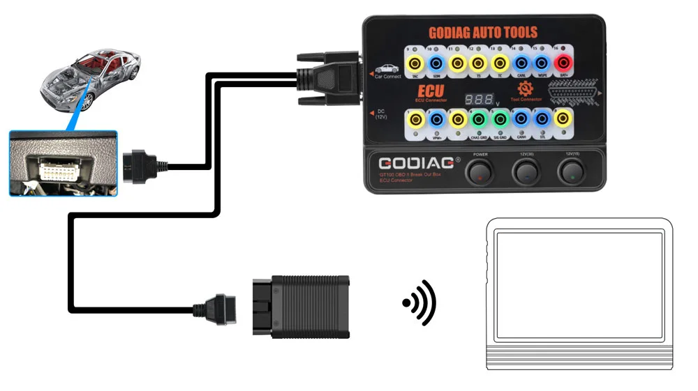
GT100 connection examples:
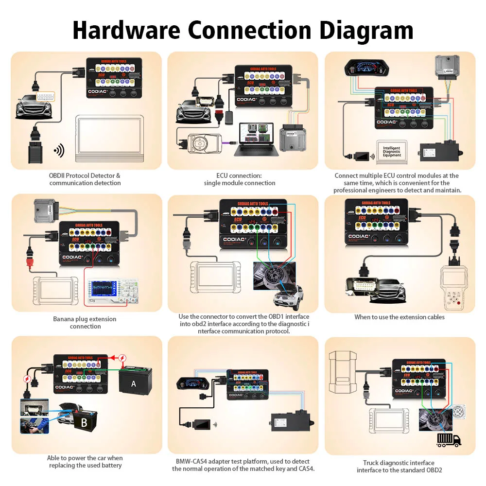
Note: The overview image illustrates different GT100 connection applications. It does not identify additional platforms, modules or diagnostic equipment as part of this bundle.
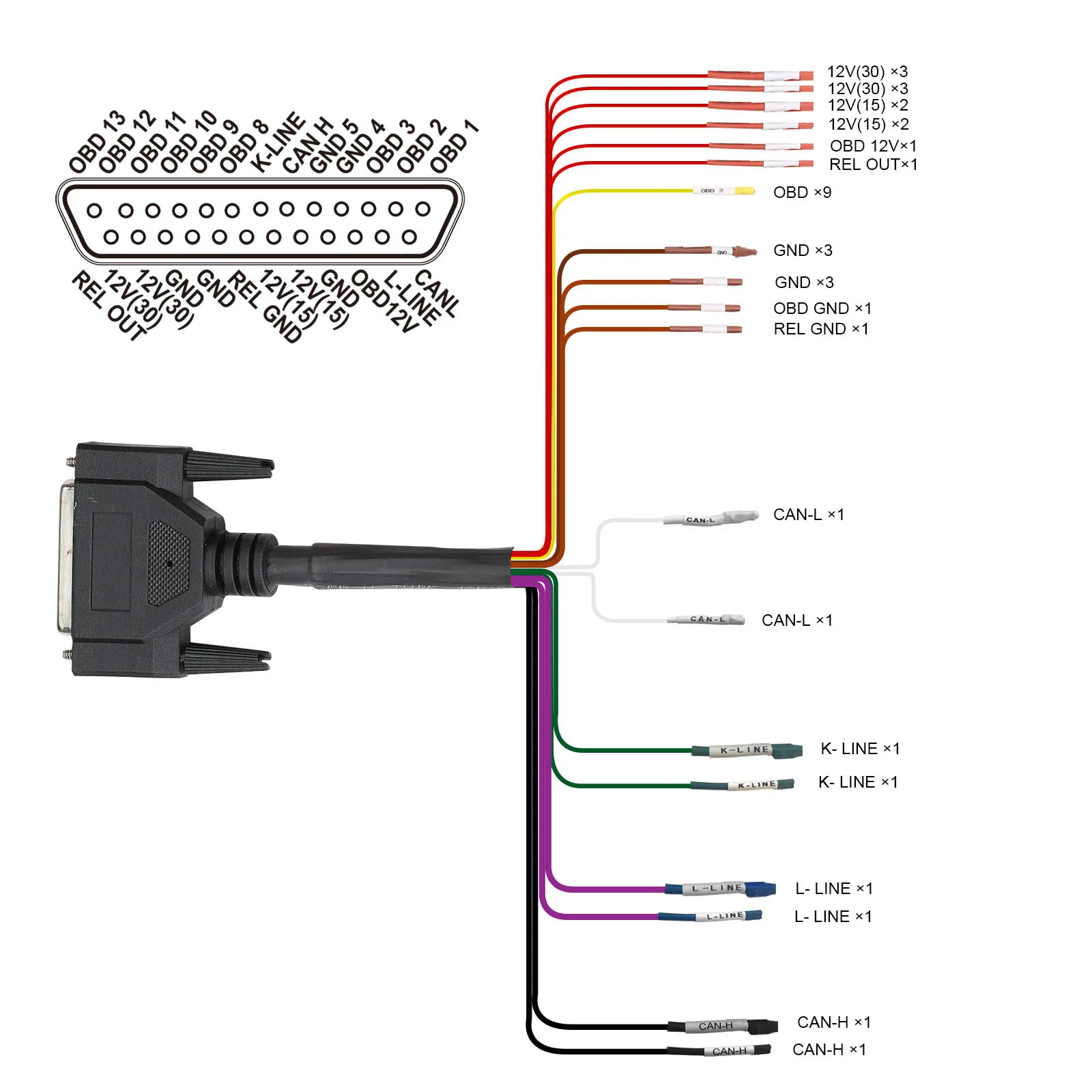
DB25 jumper-harness reference:
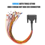
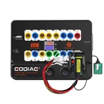
- Each OBDII pin has a 4 mm safety banana socket and a colored status LED.
- Pins 4 / 5: green ground indication; pin 16: red power indication; communication lines: blue flashing indication.
- Test leads/probes with 4 mm banana plugs connect to the corresponding safety sockets.
- The supplied front-panel description identifies three switches: one master switch and two separately switched 12V outputs for DB25 module power connections.
- Use the DB25 jumper for supported module connection and power, or the appropriate OBD1/manufacturer-specific connection.
- The appropriate AC adapter can provide an auxiliary power connection during supported battery service.
BMW FEM/BDC Bench Test Platform
The FEM/BDC platform provides module connections and a test environment for BMW immobilizer work with GT100 and compatible external programming equipment.
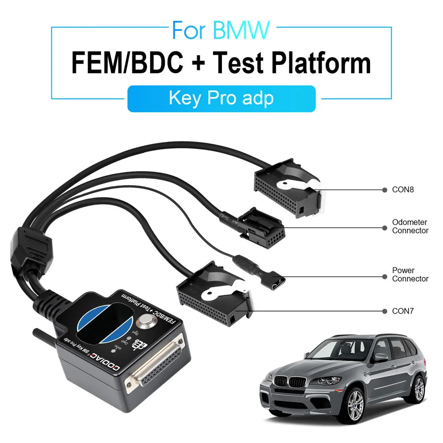
FEM/BDC Connection and Synchronization Tests
- Convenient FEM/BDC immobilizer-system connections.
- Synchronization testing between a programmed FEM/BDC module and key.
- A test environment for engineers working with recovered or reused FEM/BDC modules.
- Module/key synchronization checks for maintenance work.
- Connection support between FEM/BDC modules and the instrument cluster.
Connector illustration: CON7, CON8, instrument-cluster connector and power connector.
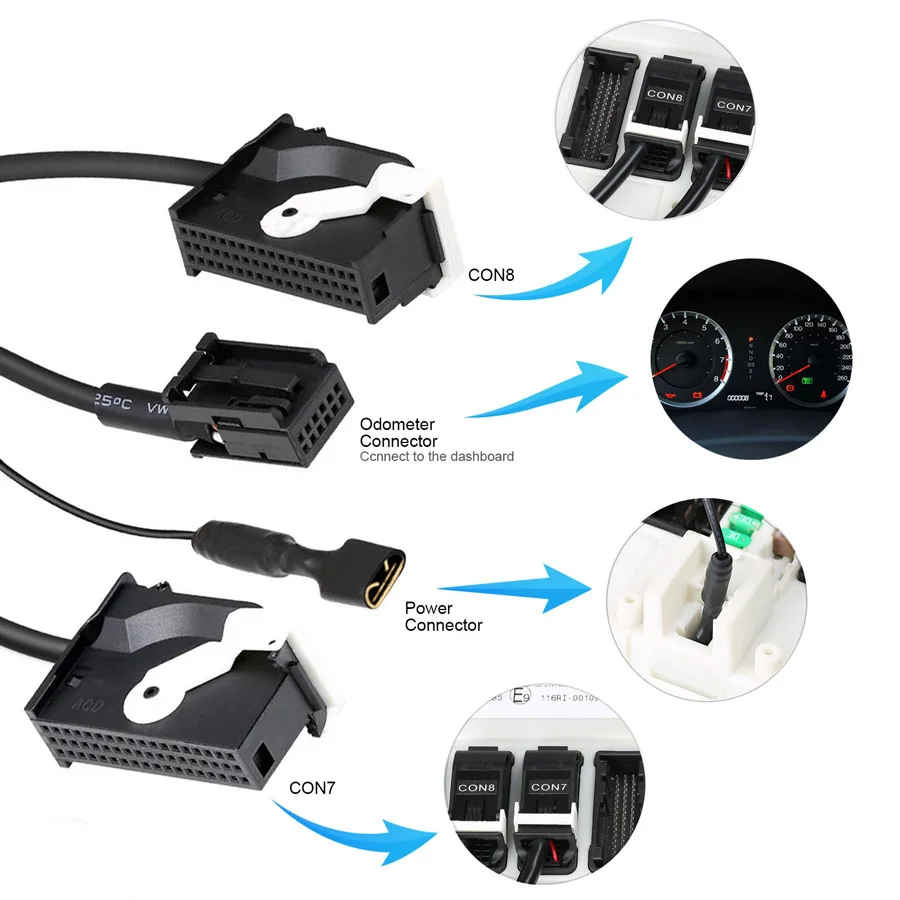
1. FEM/BDC Bench Key Programming and Module Replacement
With GT100 and compatible programming tools such as VVDI2, BMW VVDI BIM Tool, or Autel IM608, the platform supports applicable add-key, all-keys-lost, and FEM/BDC replacement workflows.
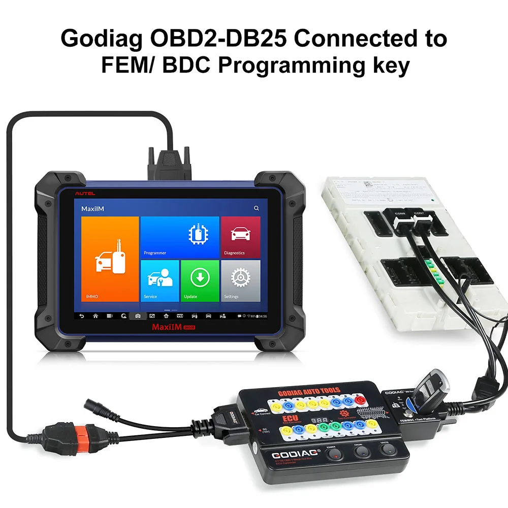
Key-service application illustration:

2. FEM/BDC Communication Checks
Connect the FEM/BDC module on the bench to check whether it communicates and investigate possible module faults with compatible equipment.
3. Data Reading and Backup After Preprocessing
Provide connection support for reading and backing up data after required preprocessing and for supported immobilizer module replacement.
Example setup using external programming equipment and a computer:
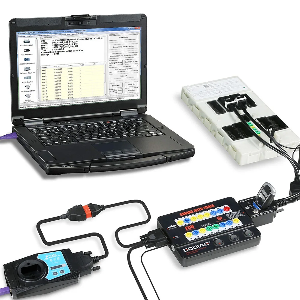
4. Key Synchronization Before Reinstallation
Test whether the programmed key synchronizes with FEM/BDC before reinstalling the module in the vehicle.
5. Remote Bench-Service Scenario
For supported key-loss service, the owner can remove the FEM/BDC module and corresponding ECU and send them to a locksmith for programming and synchronization testing.
6. Mismatch Troubleshooting
Help check whether a no-start condition is related to a mismatch between the FEM/BDC module and key.
7. Dedicated Fast Connector
The dedicated OEM-style FEM/BDC fast connector provides convenient module connection.
8. FEM/BDC Platform Controls
- DB25 female connector — connects to the DB25 male port of GODIAG GT100.
- Simulated ignition/start switch.
Compatible Equipment and Operating Conditions
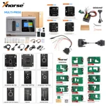
GT100 diagnostic connections are referenced with Xhorse VVDI2, Autel, Launch and Vident equipment. The FEM/BDC section also references XHORSE, CGDI and Foxwell equipment; programming examples include VVDI2, BMW VVDI BIM Tool and Autel IM608.
Note: Confirm the selected tool, software, FEM/BDC module and required operation. A connection example does not establish that every listed device supports every programming procedure.
Warranty
GODIAG GT100: one-year warranty.
Specifications
Specifications
| Parameter | Details |
|---|---|
| GT100 diagnostic port | OBDII; 16-pin breakout access |
| GT100 working voltage | DC 9–24V |
| GT100 power consumption | 0.5–0.6W |
| GT100 power adapter input | AC 100–240V |
| GT100 power adapter output | DC 12V / 1A |
| GT100 operating temperature | −20°C to 70°C (−4°F to 158°F) |
| GT100 storage temperature | −40°C to 85°C (−40°F to 185°F) |
| Diagnostic extension length | 1.2 m |
| Banana sockets | 4 mm safety type |
| GT100 display | Vehicle OBDII voltage |
| GT100 module connection | DB25 jumper; banana sockets |
| FEM/BDC platform connection | DB25 female connector; dedicated FEM/BDC module connectors |
| FEM/BDC platform control | Simulated ignition/start switch |
| External equipment | Compatible diagnostic or programming equipment required |
| GT100 warranty | One year |
Product FAQ
Ask a questionCan this GODIAG GT100 and BMW FEM/BDC kit program keys by itself?
No. This bundle provides connections and testing facilities. BMW FEM/BDC key programming requires a compatible external programmer and the applicable software support.
Can the BMW FEM/BDC test platform check a programmed key before reinstalling the module?
The GODIAG BMW FEM/BDC test platform provides a bench environment for checking synchronization between a programmed key and its FEM/BDC module before vehicle reinstallation.
Can this kit be used for BMW FEM/BDC all keys lost work?
It provides bench connections for supported BMW FEM/BDC all keys lost workflows. The external programmer must support the exact module and procedure; the platform does not perform the programming independently.
Does the GODIAG FEM/BDC platform work with Autel IM608 or Xhorse VVDI2?
GODIAG lists Autel IM608 and Xhorse VVDI2 among the external tools used with GT100 and the FEM/BDC platform. Check support for the exact module and task on the programmer.
Can this platform help when a programmed BMW key will not start the vehicle?
A BMW FEM/BDC key-synchronization test can help investigate whether the key and module are matched. It is a troubleshooting aid, not proof that every vehicle start-related fault has been resolved.
Does the included GT100 display voltage or current?
The original GODIAG GT100 displays vehicle OBDII voltage and uses protocol LEDs for communication indication. Current measurement is not a claimed function of this bundle.
Will this FEM/BDC bench test kit fit every BMW model and year?
Confirm the exact FEM/BDC module, connector and external programmer support before ordering. This listing does not establish universal BMW model-year coverage or coverage of other immobilizer-module generations.
Customer reviews
Highest rated firstNo reviews yet.