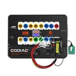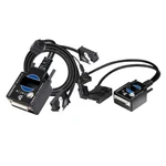

VideoGODIAG GT100+ GT100 Pro OBD2 Breakout Box with Voltage & Current Display
1 / 5
GODIAG GT100+ GT100 Pro OBD2 Breakout Box with Voltage & Current Display
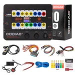
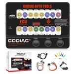
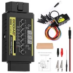
GODIAG GT100+ is a 16-pin OBD2 breakout box with voltage and current display for ECU bench connections, protocol communication checks and supported diagnostic or programming workflows using compatible external tools.
€98€109
Quantity
Delivery & shipping options
- Standard delivery
- Free
- Dispatch from
- EU
- Total incl. shipping:
- €98
- Estimated delivery
- 8–15 Working Days
- Returns
- 30 days from delivery
Frequently Bought Together
Set 1
Overview
Overview
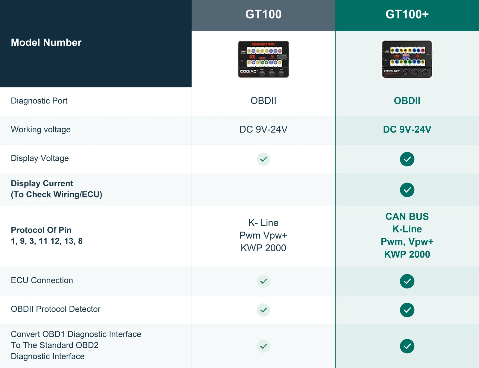
The GT100+ retains the described GT100 functions while adding ECU current monitoring through banana or DB25 connections. It provides communication checks and bench connections for supported ECU diagnosis, programming, and coding, with expanded CAN detection on specified non-standard pins. Applications include instrument/IMMO activation, OBD1 and special-truck diagnostic connections, and compatibility with BMW CAS4/CAS4+ and FEM/BDC test platforms. Programming operations require the corresponding connected tools and accessories.
Specifications
| Diagnostic Port | OBDII; 16-pin test access |
|---|---|
| Working Voltage | DC 9–24 V |
| Listed Power Consumption | 0.5–0.6 W |
| Power Adapter | Input AC 100–240 V; output DC 12 V / 1 A |
| OBD2 Cable Length | 1.4 m |
|---|---|
| ECU Connection | Banana connectors; DB25 interface; single or multiple modules |
| Listed Protocol Indication | CAN BUS; K-Line; PWM; VPW+; KWP2000 |
| Non-Standard Test Pins | 1; 9; 3; 11; 12; 13; 8 |
Showing 8 of 12 specifications
Package list
| Item | Qty |
|---|---|
| Host | 1 |
| OBD 2-in-1 extension cable | 1 |
| Colored jumper cable | 1 |
| 12V power supply | 1 |
| Item | Qty |
|---|---|
| 120Ω resistor | 1 |
| Banana plugs | 6 |
| Dupont 2.54mm female pin connectors (wire accessories) | 24 |
Description
Description
GODIAG GT100+ OBDII Breakout Box ECU Bench Connector with Voltage & Current Display
GODIAG GT100+ combines ECU connections, OBDII protocol detection, and electronic current display. It converts the vehicle OBD2 interface into 16 test connections for signal detection and supports single- or multiple-module setups with connected diagnostic and programming tools.
The supplied description lists compatibility with equipment from LAUNCH, AUTEL, FOXWELL, XHORSE, VXDIAG, and CGDI. GT100+ also provides an auxiliary power connection during vehicle battery replacement.
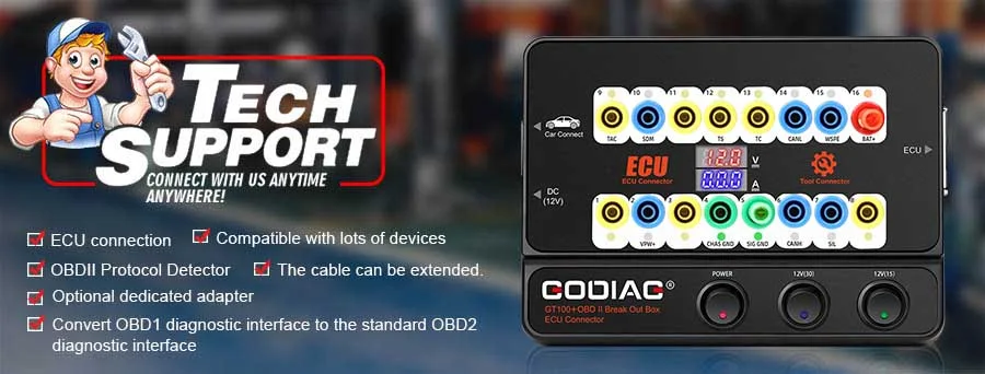
GT100+ Compared with GT100
- Retains the GT100 functions described in the supplied material.
- Adds ECU current monitoring through the banana interface or DB25 cable, alongside voltage display.
- Extends CAN communication detection on the specified non-standard / manufacturer-defined test pins.
Note: The CAN comparison concerns the specified non-standard pins. It does not mean that the standard GT100 cannot indicate CAN communication on standard CAN pins.
Communication & Supply Monitoring
Connect the vehicle and diagnostic tool through GT100+ to check OBDII communication using the LEDs. The display monitors the vehicle OBDII interface voltage in real time.
Note: If voltage is below 11 V, stop diagnosis and programming as instructed in the supplied material to reduce the risk of starting problems, data loss, or module lockout.
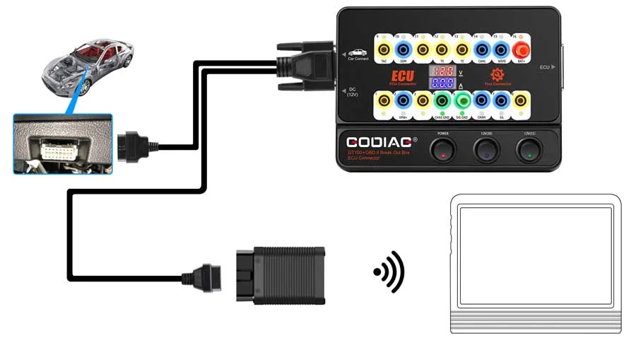
1. Diagnostic / Programming Tool Signal Check
Checks whether the connected diagnostic, programming, or coding tool sends communication signals.
2. Single ECU Module Connection
Connect one ECU module for convenient module-level diagnosis and programming using the appropriate connected tool.
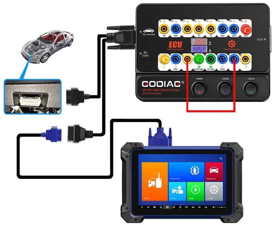
3. Instrument / IMMO Activation for Supported All-Keys-Lost Procedures
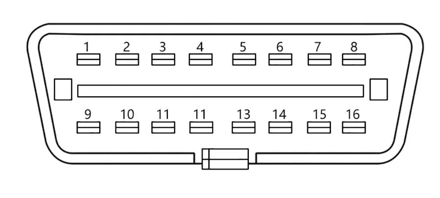
- VW / VAG 4th- and 5th-generation applications: connect banana PIN 16 to PIN 1 to activate the instrument panel, then connect the key programmer to the GT100+ female adapter for data collection. Listed examples include A6L, Touareg, A4, Q5, and A7. Some instrument panels may remain unlit while data can still be collected, including the listed A6L / Q7 examples.
- Toyota: the listed engine-ECU replacement and all-keys-lost procedures use PIN 13 to PIN 4 together with the relevant key programmer.
- Mitsubishi: the listed all-keys-lost / remote-key-loss OBDII procedure uses PIN 1 to PIN 4.
- Porsche Cayenne: the listed all-keys-lost / remote-key-loss procedure uses PIN 3 to PIN 7.
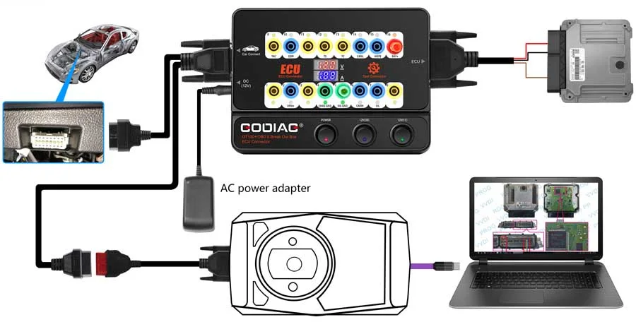
4. Voltage & ECU Current Display
On the bench, connect the ECU through the banana connectors or dedicated DB25 ECU interface to view voltage and current in real time.
Absent, unexpected, or excessive current can prompt a wiring check and help assess the ECU condition. If wiring is correct, an ECU fault may be suspected; the reading is a diagnostic clue rather than an automatic fault confirmation.
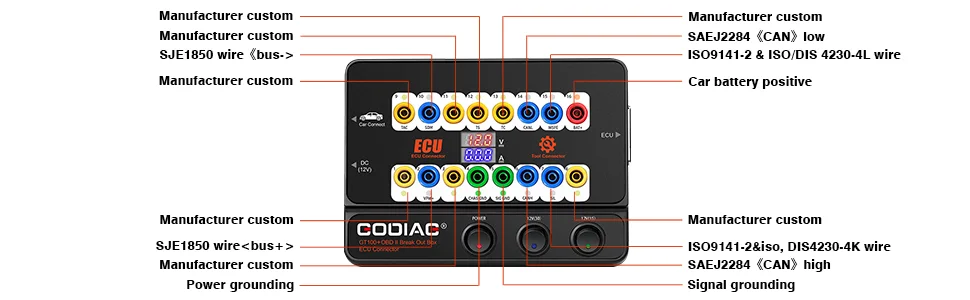
5. Expanded Protocol Indication
The supplied protocol list includes CAN BUS, K-Line, PWM, VPW+, and KWP2000.
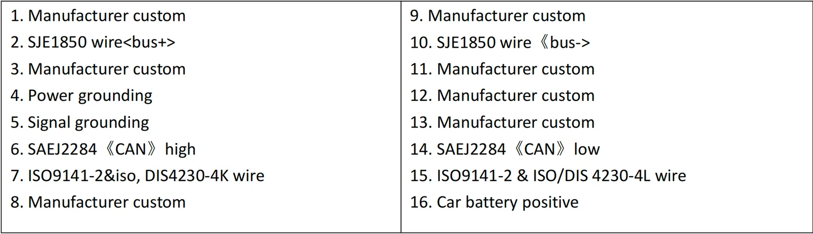
Yellow banana connectors on pins 1, 9, 3, 11, 12, 13, and 8 provide the listed non-standard OBD2 test connections, where GT100+ can indicate CAN BUS or K-Line communication.
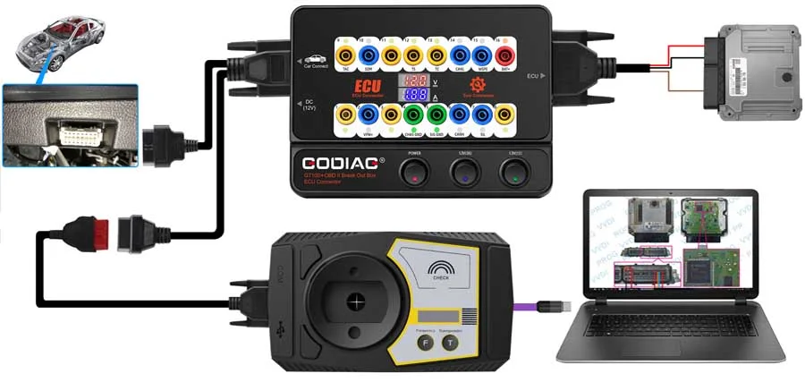
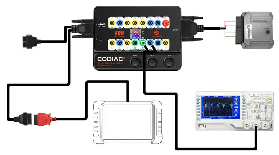
6. Direct Bench ECU Communication
Connect an ECU diagnostic or programming tool for supported direct communication with a single ECU on the bench, reducing the need to test that module while connected to the other vehicle modules.
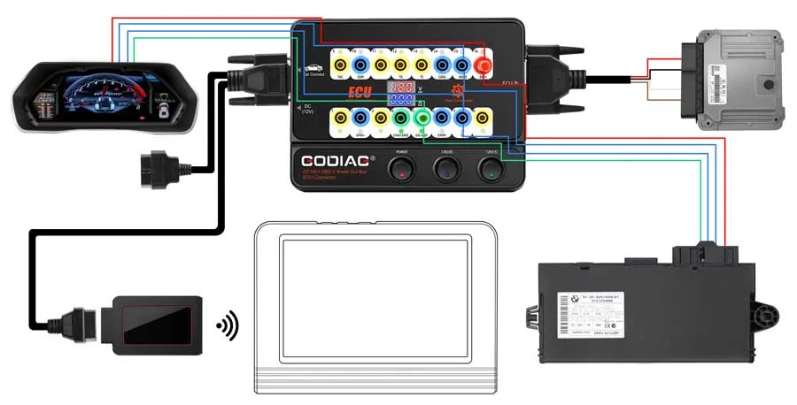
7. Multiple ECU Module Connection
Connect multiple vehicle ECU modules together for supported programming operations, including key-programming setups requiring more than one module.
8. Auxiliary Power During Battery Replacement
Connect the auxiliary power supply through GT100+ before disconnecting the vehicle battery. Maintaining the supply during replacement helps retain ECU and anti-theft remote data and avoid power-loss-related malfunction.
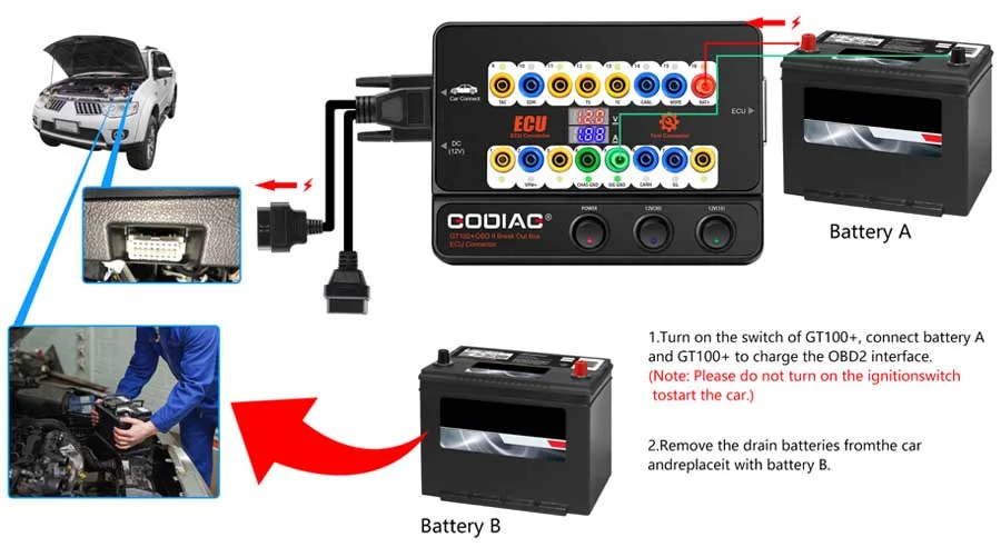
9. 1.4 m OBD2 Cable Extension
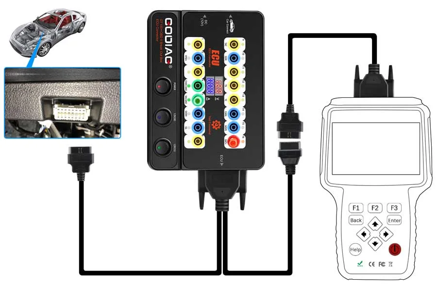
The 1.4 m OBD2 cable assists when the diagnostic tool cable is too short or the vehicle diagnostic port is difficult to access.
Connect GT100+ first and turn ON its power switch to view the supply voltage before connecting the diagnostic / programming tool. This provides a preliminary power check, including on vehicles with a modified OBD2 port.
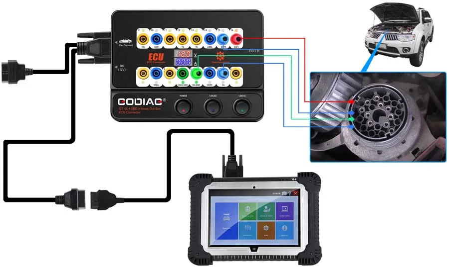
10. OBD1 / Special Diagnostic Port Conversion
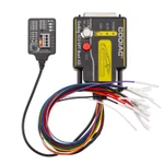
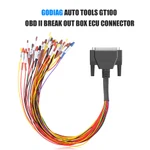
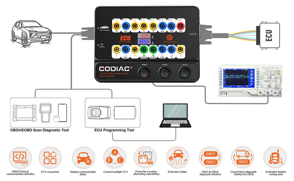
Use the banana connections and DB25 jumper to connect older OBD1 vehicles or special diagnostic interfaces to the standard OBD2 diagnostic connection.
11. Special-Truck Diagnostic Port Conversion
Provides the listed OBD1-to-OBD2 connection arrangement for special trucks according to the relevant communication protocol.
The following original diagram is shared by Functions 10 and 11.
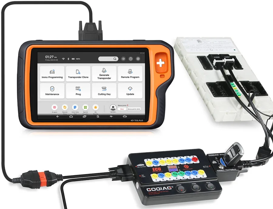
12. BBMW CAS4/CAS4+Programming Test Platform
Used with the corresponding BMW CAS4 / CAS4+ Programming Test Platform to check whether a programmed key works with the CAS4 module.
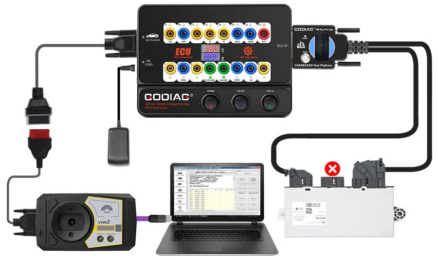
13. BMW FEM/BDC Programming Test Platform
Also works with the corresponding BMW FEM/BDC Programming Test Platform.
Note: These BMW functions require the specified test platform and relevant programming equipment. They are compatibility descriptions, not a claim that the BMW platforms are included.
14. Listed Connection Accessories
- DB25 jumper cable.
- 24 wire accessories.
- 6 banana plugs.
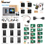
15. Additional Dedicated Connectors & Modules
The supplied product material refers to further dedicated connectors and modules as being under development. The original connection reference below is retained for illustration.
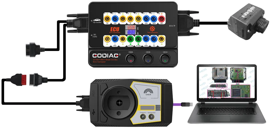
Hardware Connection Diagram
Warranty & Dispatch
One-year warranty, as stated in the supplied offer.
Specifications
Specifications
| Parameter | Details |
|---|---|
| Diagnostic Port | OBDII; 16-pin test access |
| Working Voltage | DC 9–24 V |
| Listed Power Consumption | 0.5–0.6 W |
| Power Adapter | Input AC 100–240 V; output DC 12 V / 1 A |
| OBD2 Cable Length | 1.4 m |
| ECU Connection | Banana connectors; DB25 interface; single or multiple modules |
| Listed Protocol Indication | CAN BUS; K-Line; PWM; VPW+; KWP2000 |
| Non-Standard Test Pins | 1; 9; 3; 11; 12; 13; 8 |
| Operating Temperature | −20 to 70 °C |
| Storage Temperature | −40 to 85 °C |
| Listed Connection Accessories | DB25 jumper cable; 24 wire accessories; 6 banana plugs |
| Warranty | 1 year, as stated in supplied offer |
Compare
Compare
Downloads
Product FAQ
Ask a questionCan I connect an OBD2 scanner to an ECU on the bench using the GODIAG GT100+?
Yes, for supported modules and tools. GODIAG GT100+ provides 16-pin breakout access and module connections so you can connect an OBD2 scanner to an ECU on the bench. Use the correct module pinout, power supply and compatible diagnostic equipment. Reading, programming and coding functions depend on the connected tool and its software.
Why does my ECU have power but no communication through the GT100+?
For ECU bench testing with no communication, verify the module-specific connections, supply voltage and support provided by your diagnostic tool. The GT100+ displays voltage and ECU current and provides protocol activity indicators to help assess the setup. A power reading alone does not confirm that the module is ready to communicate or that the selected diagnostic function is supported.
What does a zero or unexpected current reading mean during ECU bench testing?
During ECU bench testing with a zero current reading, check the module connections and supply requirements before suspecting an ECU fault. GODIAG GT100+ displays voltage and current when the ECU is connected through the banana connectors or DB25 interface. An unexpected reading is a troubleshooting clue; it does not by itself confirm that the ECU is defective.
Can the GT100+ test a used ECU before installation?
GODIAG GT100+ supports single-module connections that can help you bench test a used ECU before installation with compatible diagnostic equipment. The checks available depend on the module and connected tool. Treat communication and current readings as preliminary diagnostic information, rather than proof that every ECU function will operate correctly in the vehicle.
Can I use the GT100+ for ECU reading or cloning without opening the ECU?
ECU reading or cloning without opening the ECU depends on the specific module and the supported procedure of your programming tool. GODIAG GT100+ provides ECU connection access and voltage/current monitoring; it does not independently read, write or clone ECU memory. Confirm the required programmer, software, protocol and accessories before choosing a bench workflow.
What is the difference between GT100 and GT100+ for ECU bench work?
For a GT100 vs GT100+ comparison, the key upgrade is ECU current monitoring through the banana connectors or DB25 cable, alongside voltage display. The manufacturer also lists expanded CAN communication indication on specified non-standard test pins. This distinction does not mean the standard GT100 lacks CAN indication on standard CAN pins. Choose according to your monitoring and connection requirements.
Customer reviews
Highest rated firstNo reviews yet.