

OBD-II provides a standardized vehicle diagnostic connection, but a 16-position connector does not mean that all 16 terminals are populated, or that every connected tool supports every electronic control module. This guide explains the connector, its common pin functions, relevant communication standards, and safe ways to select diagnostic equipment.
1. What Is the OBD-II Diagnostic Connector?
The standardized Data Link Connector (DLC) is a vehicle-side diagnostic connection that can be used with compatible external test equipment. SAE J1962 and ISO 15031-3 address connector requirements and relevant contact usage. The familiar interface has 16 contact positions arranged in two rows of eight.
The physical appearance may vary in housing color and installation location; however, the connector type, electrical use and any populated contacts must be checked for the actual vehicle. A connector alone cannot establish support for ECU coding, programming or cloning.
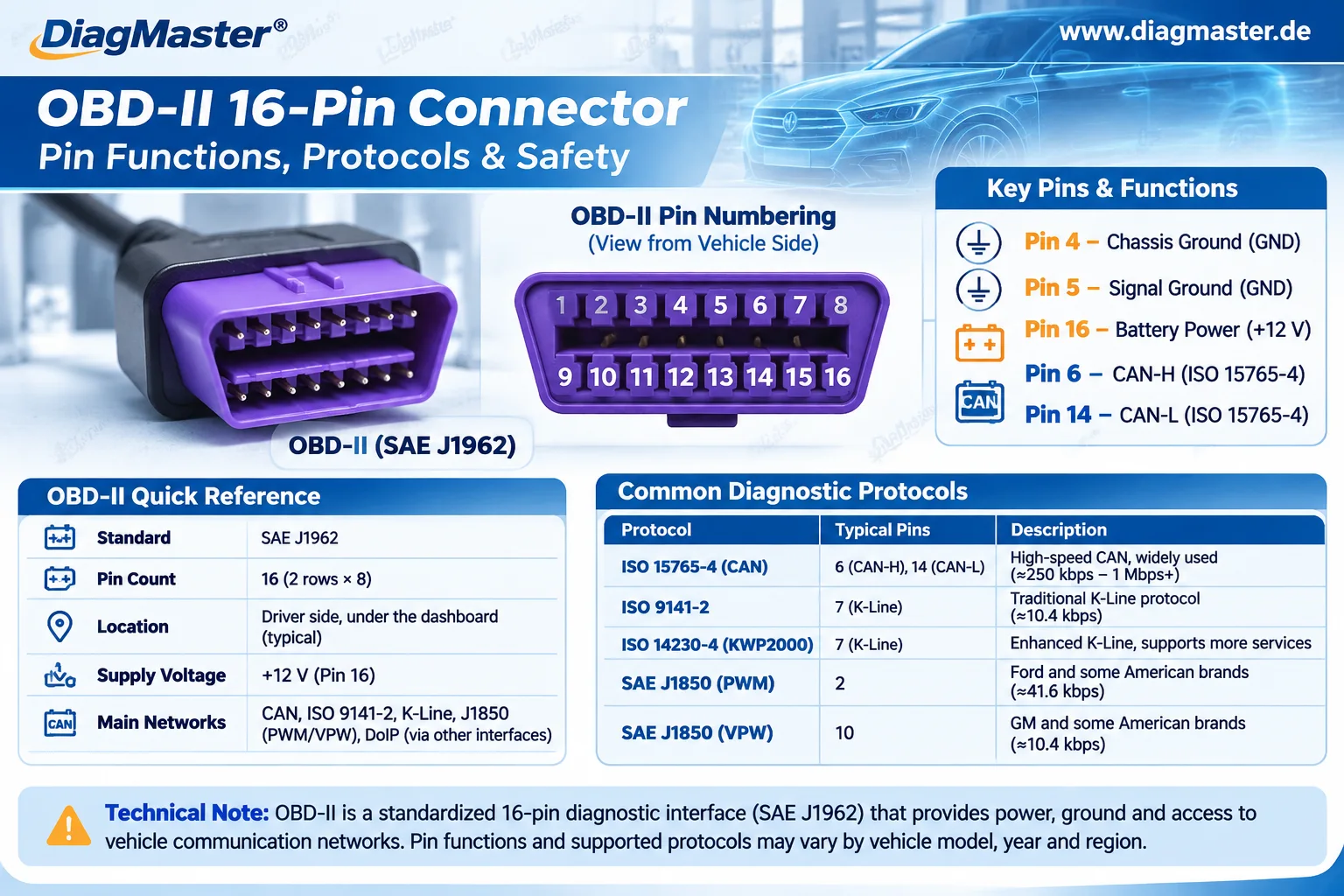
Figure 1. Type A mating-face reference view with two rows of eight contact positions; the purple socket is a real photo supplied for visual reference. Not an OEM wiring diagram.
Orientation matters
The numbering shown in Figure 1 is for the mating face of the vehicle-side connector with the wider edge at the top. A view from behind the connector, or a plug viewed from the opposite side, is mirrored. Never wire a module from a photograph alone.
2. OBD-II Pin Numbers and Common Functions
Pin | Common function | Interpretation / limitation |
4 | Chassis Ground | Vehicle grounding reference; verify the appropriate test reference in service information. |
5 | Signal Ground | Diagnostic signal return; do not assume every return path is interchangeable. |
6 | CAN High (CAN-H) | Used for emissions-related diagnostics over CAN where the applicable protocol is implemented. |
14 | CAN Low (CAN-L) | CAN pair with pin 6 for applicable diagnostic CAN implementations. |
16 | Vehicle Battery Positive | Power supplied by the vehicle; voltage depends on vehicle/interface type, so do not assume 12 V universally. |
7 | K-Line | Used by some legacy ISO 9141-2 / ISO 14230 diagnostic implementations. |
15 | L-Line | Optional legacy initialization line where implemented. |
2 / 10 | SAE J1850 lines | Relevant to certain older J1850-based implementations; not universal. |
Other positions | Vehicle-/protocol-dependent | Do not treat unused positions as safe to bridge, short, or power. |
16 positions ≠ 16 installed terminals
Many vehicle connectors do not contain a populated metal contact at every position. Also, standardized signal assignments apply to the relevant protocol rather than every vehicle on the road.
3. Connector Standards vs Communication Protocols
Reference | What it addresses | Do not confuse it with |
SAE J1962 | OBD diagnostic connector and electrical/contact requirements | A guarantee of ECU software access or programming |
ISO 15031-3:2023 | Diagnostic connector and associated circuit usage; references SAE J1962 | The vehicle’s full network architecture |
ISO 15765-4 | CAN-based emissions-related diagnostic communication | The connector shape or pin housing dimensions |
ISO 9141-2 / ISO 14230 | Certain legacy serial diagnostic communications | A modern universal CAN diagnostic standard |
DoIP / ISO 13400 | Diagnostics over Internet Protocol (often Ethernet based) | A synonym for CAN or a guaranteed feature of every 16-pin socket |
SAE J2534 | PassThru vehicle interface API for supported applications | Automatic OEM software access, licenses or all-vehicle coverage |
A vehicle may use different diagnostic pathways for different modules. The presence of an OBD connector does not identify the full protocol set, manufacturer-specific gateway restrictions, security authorization or programming access.
4. What Can a Compatible OBD Tool Do?
- Read supported Diagnostic Trouble Codes (DTCs) and relevant vehicle data.
- View available live values and freeze-frame information.
- Perform selected actuator tests, service functions or adaptations if supported.
- Access specific OEM diagnostic features when appropriate software and authorization are available.
- Execute ECU programming only when the exact vehicle, controller, interface, procedure and licensing support it.
Diagnostic communication is not the same as repair
Clearing a DTC can remove a stored indication, but it does not resolve the underlying fault. A valid repair requires diagnosis, corrective work and verification.
5. Choosing an Interface: Scanner, PassThru or Breakout Box
Tool type | Typical role | Example / key limitation |
OBD communication adapter | Links suitable diagnostic software to the vehicle for supported functions | GODIAG GT327 class; software and protocol support must be checked |
J2534 PassThru interface | Supports compatible software communicating through a standardized interface API | GODIAG GD101 class; manufacturer functions and authorization not guaranteed |
DoIP / ENET adapter | Provides the required physical/IP connection in supported vehicles | GODIAG GT109 class; not a self-contained diagnostic application |
OBD breakout box | Exposes or routes defined pins for suitable electrical examination or connection | GODIAG GT100 / GT100+ class; not a standalone ECU programmer |
6. Common Workshop Scenarios
Scenario A: The check-engine light is illuminated
Use compatible diagnostic equipment to collect DTCs, freeze-frame information and relevant live data. Apply the manufacturer diagnostic procedure to confirm the cause rather than replacing a component based only on a fault-code label.
Scenario B: A scan tool cannot communicate
Identify the correct vehicle and diagnostic access requirements. Follow OEM information to investigate power, ground, connector condition, interface compatibility and communication-network faults; do not short adjacent pins or inject power into an unidentified terminal.
Scenario C: A customer requests ECU flashing or cloning
Confirm the exact ECU/TCU model and part number, required read/write operation, tool support matrix, software/license, required connection mode and stable power requirements. OBD connection alone does not establish that a module can be programmed or cloned.
7. Frequently Asked Questions
Does OBD-II always have 16 metal pins?
No. The connector provides 16 standardized contact positions; some may be unpopulated on a specific vehicle.
Are pins 6 and 14 always CAN on every car?
They are the standard CAN diagnostic positions for applicable CAN implementations. Check the actual vehicle and protocol before testing.
Is pin 16 always exactly 12 volts?
No. It is the vehicle-battery-positive position, and the applicable supply requirements depend on connector type and vehicle system.
Does a 16-pin OBD connection guarantee OEM programming?
No. Access depends on the vehicle, ECU, security requirements, interface, manufacturer software, licenses and support list.
Can a breakout box diagnose the vehicle on its own?
No. A breakout box provides circuit access or routing; appropriate diagnostic/test equipment and correct procedures are still required.
8. Safety and Compatibility Checklist
- Identify the vehicle, model year and diagnostic connector type.
- Confirm the exact viewing orientation and intended test points.
- Check manufacturer pinout and circuit diagrams before probing.
- Verify battery system voltage and equipment compatibility.
- Use insulated, appropriate test probes and avoid adjacent-terminal shorts.
- Confirm the exact diagnostic, coding or programming capability before purchasing a tool.
- Preserve diagnostic records and follow service procedures.
Safety notice
This guide is for education and purchasing decisions, not direct wiring or control-module repair instructions. Follow applicable OEM service documentation and use qualified personnel for electrical, programming, immobilizer and safety-critical work.
9. Explore Relevant DiagMaster Tools
See OBD Diagnostic and ECU Bench Tools for current products and configurations. Always verify accessories, supported operations and coverage for the specific product listing.
This educational article summarizes general OBD connector and diagnostic principles. It is not an OEM wiring diagram, not a manufacturer coverage list, and not an assurance of compatibility for a specific vehicle or ECU.