

Understand the electronic systems behind modern automotive diagnostics and follow a structured workflow from customer complaint to verified repair.
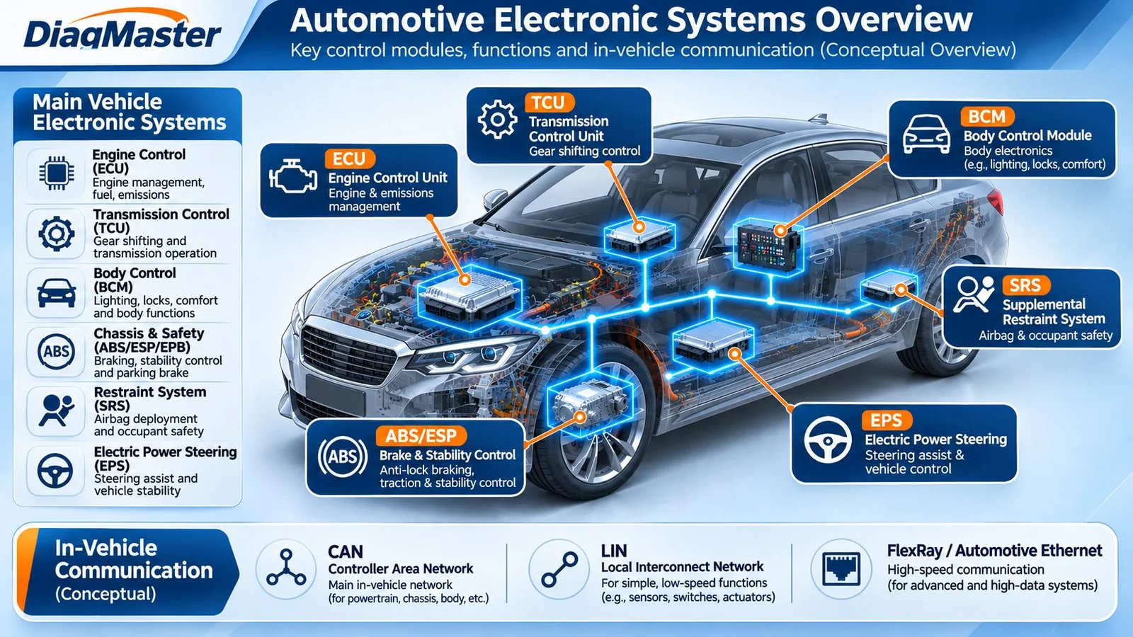 Concept illustration: major vehicle modules and communication networks. Diagram locations are illustrative, not OEM schematics.
Overview: The Main Vehicle Control Systems
System | Abbreviation | Typical responsibility |
Engine management | ECU / ECM / DME | Engine control including fuel injection and ignition where applicable |
Transmission | TCU / TCM | Shifting logic and related transmission control |
Body electronics | BCM | Selected lighting, locking and window functions |
Immobilizer | IMMO | Key authorization and engine-start permission |
Safety restraints | SRS | Airbag and restraint-system monitoring/control |
Instrument cluster | Cluster | Vehicle information and warning displays |
Network gateway | Gateway | Routing/management of traffic between designated vehicle networks |
How Modules Communicate
Network | Meaning | Practical relevance |
CAN | Controller Area Network | Robust serial communication between controllers |
CAN FD | CAN with Flexible Data-Rate | Enhanced CAN with larger data fields and potentially higher data rates |
LIN | Local Interconnect Network | Lower-cost communication for selected local body functions |
DoIP | Diagnostics over Internet Protocol | IP-based diagnostic communication, commonly using Ethernet |
Remember
DoIP is a diagnostic communication approach over IP, not another name for the CAN bus. Actual module layouts differ across brands and model years.
A Six-Step Diagnostic Workflow
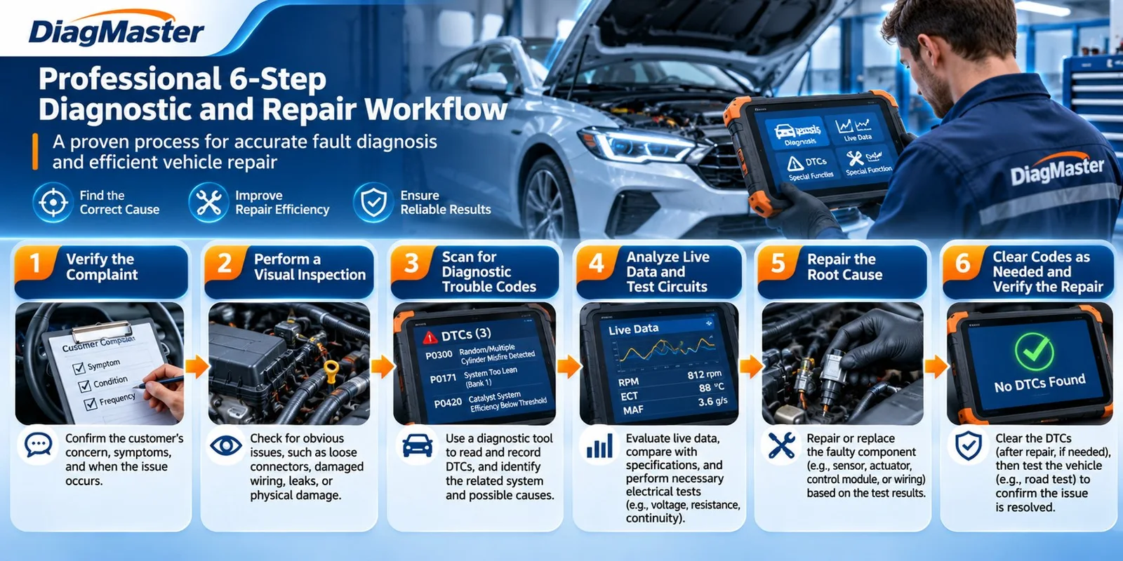 Figure 2. Conceptual six-step process; follow vehicle-specific diagnostic procedures. Illustrated display values are not actual test results.
Step | Action | Outcome |
01 | Confirm symptoms, model, year, VIN and battery condition | Clear repair request |
02 | Read/save DTCs, freeze-frame and live data | Original diagnostic evidence |
03 | Check fuses, supply, grounds, connectors and wiring | Basic causes ruled in/out |
04 | Use wiring diagrams, measurements and supported tests | Evidence-based root-cause decision |
05 | Repair wiring/parts or perform supported coding/programming | Correct repair for diagnosed condition |
06 | Retest, road-test where appropriate and document | Verified operation and service record |
Diagnosis, Coding and Programming Are Not Interchangeable
Task | What it does | What it does not establish |
Diagnosis | Reads codes, live data and performs supported tests | A DTC by itself does not identify the defective part |
Coding / Adaptation | Configures settings or performs supported learning/matching | Not necessarily raw memory read/write |
Programming / Flashing | Reads/writes supported control-unit software or data | Not equivalent to clearing codes |
Critical repair principle
Clearing diagnostic trouble codes does not resolve the underlying defect.
Typical Workshop Applications
The diagnostic process changes with the reported symptom. These examples describe tool categories, not guaranteed compatibility with any individual vehicle.
- Engine warning lamp: Retrieve DTCs and relevant live data; investigate the related system before replacing parts.
- Intermittent module communication: Verify power, grounds, relevant wiring and network conditions before assuming a control unit has failed.
- Replacement control unit: Confirm the exact part number and manufacturer procedure, including any required coding, adaptation or programming.
Diagnostic Tool Selection Checklist
- Identify the vehicle make, model, model year and relevant module part number.
- Define the task: diagnostic reading, circuit testing, coding, adaptation or programming.
- Check the required communication protocol, software version and authorization.
- Confirm cables, adapters and manufacturer-specified power requirements.
- Review current tool support documents and applicable OEM service procedures.
Tool boundary: A J2534 pass-through interface, an OBD breakout box and an ECU programmer are different product categories; the accessory itself does not necessarily provide full diagnostic or programming capability.
Frequently Asked Questions
Does a DTC prove a sensor is defective?
No. The fault may involve the circuit, power, ground, connector, wiring, operating conditions or the sensor itself.
Why record data before clearing codes?
Saved DTCs, freeze-frame and live data preserve context for troubleshooting and post-repair comparison.
Technical scope
This guide is educational. Vehicle-specific functions, access methods, and safe procedures must be confirmed against current OEM service information and the exact tool/ECU compatibility list.