

Abstract
OBD, Bench and Boot describe ECU/TCU access approaches used by programming-tool manufacturers. Each method must match the exact controller, intended operation and tool instructions. This guide explains equipment roles and selection criteria; it is not a wiring or programming procedure. [R03]
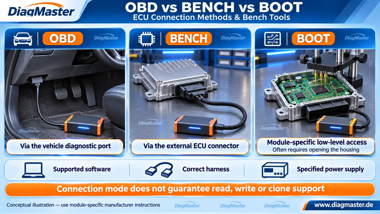
Figure 1. Conceptual access arrangements, not a wiring diagram. Housings, cables and board contacts are illustrative. Bench and Boot setup requirements vary by manufacturer and controller. Sources: R01, R02 and R10.
1. Definitions: what the three modes describe
Table 1. Common programmer terminology; exact protocol instructions take precedenceMode | Working definition | Housing / installation |
|---|---|---|
OBD | Tool access through the vehicle diagnostic connector. In this context, “OBD mode” describes the connection route. | Usually performed with the controller installed. |
Bench | Direct access through the controller’s external connector using a specified harness. | Commonly a closed controller on a workbench; removal rules are tool-specific. |
Boot | A controller/MCU-specific low-level access procedure. | Often involves an opened housing and a probe, adapter or board connection; the exact method varies. |
Connection terminology:
Alientech describes these as diagnostic-port, external-connector and open-controller approaches. AutoTuner’s universal-cable instructions demonstrate that accessories and operating conditions are defined for each workflow. These labels describe access arrangements, not an industry-wide promise of identical functionality. [R02]
Physical location is not a protocol
Putting a controller on a workbench does not prove that software is using the vendor’s Bench protocol. Likewise, the name printed on a tool connector does not determine the selected operation: AutoTuner’s documented Bench setup uses its tool connector marked “BOOT”. Read the software protocol and module instructions. [R02]
2. OBD: convenient access still needs exact support
OBD access can avoid controller removal, but the software must still support the required function on that exact ECU/TCU. Alientech’s support legend distinguishes reading, virtual reading, an unlock requirement and cloning. A listed vehicle or an available identification function is insufficient evidence that the same connection can produce a backup or clone. [R03]
Actual read and virtual read are different. AutoTuner defines normal reading as data read from the connected ECU; its virtual reading downloads a stock file corresponding to the software identification. A virtual read therefore does not capture an existing modified calibration or the module’s unique persistent data. Record the file’s origin before describing it as a backup. [R04]
J2534 is a separate interface concept. The cited SAE scope describes a standardized PC-to-vehicle interface, with vehicle-manufacturer software controlling actual reprogramming. It does not define “OBD/Bench/Boot” as universal capability levels or supply every OEM application and firmware file. Select the application and interface specified for the job. [R05]
3. Bench: direct connector access
Bench commonly means external-connector access without opening the housing. It can be useful when the selected operation is offered through a direct controller connection rather than the vehicle diagnostic connector. It still depends on a supported protocol, correct connector mapping and the prescribed supply arrangement. [R01]
Removal requirements differ between manufacturers
Alientech describes selected applications that can be connected in the engine bay. AutoTuner’s ATUC051 instructions explicitly require removal and prohibit Bench reading/writing with the ECU in the engine compartment. Neither instruction can be transferred to another product. Follow the exact tool/module procedure you are using. [R01] [R02]
4. Boot: low-level access with controller-specific limits
Boot access may require board contacts, a fixture or an adapter and, for some applications, soldering. The connection drawing must match the controller hardware. Opening the housing alone does not establish a valid access path, and a probe touching a familiar-looking pad is not evidence of the correct connection. [R01] [R02]
Low-level access does not automatically remove hardware protection. Infineon’s AURIX TC3xx manual describes interactions between flash read protection, debug locking and the hardware security module (HSM), and notes that OTP protection cannot be removed. The service implication is conditional: determine whether the specific controller and documented tool procedure expose the data needed for the task. Do not generalize the chip example into a universal unlock or recovery method. [R06]
5. A bench setup needs complementary equipment
Table 2. Equipment roles: planning checklist, not a wiring sequenceItem | Its role | What to confirm |
|---|---|---|
Main programmer or diagnostic interface | Executes the selected communication/programming function. | Exact controller, operation and mode support; software/license requirements. |
Harness / cable / adapter | Connects the required tool and controller points. | Connector variant, hardware revision, orientation and documented pin map. |
Breakout box / connection platform | Provides accessible connections or a convenient controller setup. | Electrical ratings and the separate tool required to perform the operation. |
Power equipment | Supplies the required operating conditions. | Specified voltage, current capability, grounding and connection sequence. |
Protocol instructions and software | Define the supported workflow. | Applicable manual revision, prerequisites, file scope and completion checks. |
The GODIAG GT100 manual illustrates the division of roles: its single-controller section calls for a separate diagnostic tool or ECU programmer. A breakout box can assist the connection; it does not acquire a programmer’s missing software protocol by itself. An indicator light or voltage display is not proof of a verified memory write. [R08]
Power requirements must come from the exact procedure. For example, GM bulletin N232428540-02 specifies stable voltage and approved programming support equipment and warns that interruption can cause failure or damage. That historical bulletin concerns specified 2023 LYRIQ vehicles; its instructions are not a general supply recipe for a loose ECU. Do not treat an accessory’s input-voltage range as the permissible supply range for every controller. [R07]
6. Match the method to the task
Use the following evidence-based planning questions. The decision rules are DiagMaster’s editorial synthesis, not a manufacturer-issued universal procedure.
Table 3. Capability evidence matters more than the connection labelIntended task | Evidence to obtain before proceeding | Assumption to avoid |
|---|---|---|
Identify the module | Correct part number and hardware/software identifiers; supported connection. | Identification success means all memory is accessible. |
Update software or calibration | Supported write operation and correct file/OEM package. | A readable file is necessarily the correct writable file. |
Preserve original data | Actual read availability, included regions and restoration conditions. | Virtual read or a large file equals a complete backup. |
Replace or clone | Explicit support for the donor/original relationship and required data transfer. | Bench or Boot automatically means clonable. |
Recover after a failure | A documented recovery function for the exact controller and failure state. | Every failed OBD write can be repaired in Boot mode. |
7. Before connection, before writing, after writing
- Before connection: identify the controller, define the job, and obtain the exact connection instructions. Check the harness, power arrangement and permitted installation/removal state.
- Before writing: confirm supported functions, file provenance, available backup coverage and the documented recovery path. Preserve identifiers and operation logs.
- During the operation: follow the tool/OEM sequence and interruption instructions. Stop if the observed setup or controller identity does not match the selected documentation.
- After writing: perform the specified verification, reinstallation and diagnostic/functional checks, including any required coding or relearn. Record unresolved faults before closing the job.
This checklist helps organize a service decision. It does not specify terminal numbers, a universal resistor value, a supply setpoint or an ECU-opening method. Those details must come from the exact manufacturer procedure. A completed transfer and a verified vehicle repair are different acceptance criteria.
8. Frequently asked questions
Does Bench always require opening the ECU?
No. Bench usually refers to access through the external connector with the housing closed. Removal rules remain tool-specific. [R02]
Can I leave the ECU in the engine bay for Bench work?
Only if the exact manufacturer procedure allows it. AutoTuner’s ATUC051 procedure forbids this, while Alientech describes selected in-bay applications. Do not interchange those instructions. [R01] [R02]
Does a BOOT-labelled tool socket mean the ECU is in Boot mode?
No. AutoTuner documents Bench use of its BOOT-labelled socket. Follow the selected software protocol and ECU procedure. [R02]
Does OBD reading always capture the ECU’s current contents?
No. Check whether the function is an actual read or a virtual read. A stock server file does not preserve current modifications or unique ECU data. [R04]
Does Boot guarantee a full read or a successful clone?
No. Memory protection and controller-specific tool support still apply. Confirm the required readable/writable regions and explicit cloning support. [R03] [R06]
Can a breakout box program an ECU on its own?
Do not assume so. The GT100 manual describes using a separate diagnostic tool or ECU programmer for single-module operations. [R08]
Is one power setting suitable for every bench setup?
No. Use the exact controller/tool specification. An accessory’s input rating is not a universal ECU supply specification.
Which connection method is best?
Use a supported method that meets the exact task and procedure. The most invasive connection is not automatically the most suitable, and physical access alone does not establish software capability.
9. Related tools and resources
Table 4. Topic-related products; association is not a compatibility certificateRelated product | Role in the setup | Selection boundary |
|---|---|---|
OBD breakout box / ECU connection platform | Used with a suitable diagnostic tool or programmer; not a standalone universal ECU flasher. | |
Programming system advertising OBD, Bench and Boot mode families | Confirm exact module, operation, mode, software/license and accessories; no universal read/write/clone claim. |
The GT100 manual and FormulaFlash product overview support these category descriptions. Product links lead to DiagMaster listings checked for identity on 17 November 2026. Specific controller coverage, current license entitlements and bundle contents must be checked separately. [R08]
Technical references
Sources checked 17 November 2026. Manufacturer terminology is kept within its stated scope. Ten concise references are listed here; the separate source register records evidence and access limits.
[R01] Alientech. Connection Methods. KESS3; OBD / Bench / Boot sections
[R02] AutoTuner. Universal cable + universal box (ATUC051). Régis Thomas; July 10, 2026; Bench / Boot / Universal box
[R03] Alientech. KESS3 & Powergate Vehicle List. Legend / Connections / Connection Functions
[R04] AutoTuner. Virtual Read vs Normal Read. Régis Thomas; June 6, 2025; Virtual read / Normal read
[R05] SAE International. J2534-1_0500_202201 — Recommended Practice for Pass-Thru Vehicle Programming. Issued January 5, 2022; public Scope; DOI 10.4271/J2534-1_5_00
[R06] Infineon Technologies. AURIX TC3xx Family User’s Manual, Part 1. V2.0.0, February 2021; §6.5.4.4 System Wide Effects of Flash Protection; printed p. 6-159
[R07] General Motors, hosted by NHTSA. N232428540-02 — Multiple Module Reprogramming. Revision 02, August 2024; Service Procedure; printed p. 2, PDF p. 3
[R08] GODIAG. GODIAG GT100 — Overview. §4 Function and operation guide; single-module connection; PDF pp. 4–5
[R09] VAPON Technology / FormulaFlash. FormulaFlash — Professional ECU & TCU Reprogramming Tool. Product page / OBD, BENCH and BOOT modes
[R10] Alientech. KESS3. Connections; ECU, TCU and cloning FAQ
Technical scope
Prepared for DiagMaster Technical Support as an educational technical explainer. It is not an OEM repair bulletin, a wiring reference or a certification of tool compatibility. Follow current tool documentation and applicable vehicle service information. www.diagmaster.de.