

Abstract
SRS diagnosis and ordinary automotive circuit testing share the need for evidence, but they do not share every test method. Airbags and pyrotechnic pretensioners require the exact vehicle’s restraint-system procedures. Clearing diagnostic faults or changing module data cannot repair deployed or damaged restraint components. This guide separates scan-based SRS evaluation from suitable low-voltage circuit measurements and explains the limits of related workshop tools.
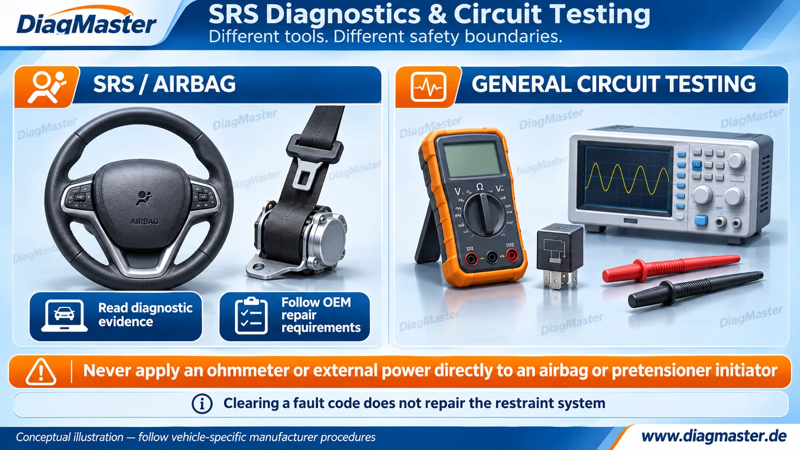
Figure 1. Conceptual SRS and general-test equipment illustration. No measuring lead is connected to a restraint device. Instrument controls are illustrative. Original DiagMaster editorial artwork.
1. What SRS diagnosis must establish
SRS means Supplemental Restraint System. Depending on the vehicle, it includes airbags, restraint-control electronics, relevant sensors, wiring and belt-pretensioning components. A warning lamp or DTC reports a diagnostic condition; it does not by itself identify the defective part or establish whether a post-collision vehicle is ready to return to service.
Keep test instruments away from pyrotechnic initiators
Do not apply an ohmmeter, continuity tester, test light or external power directly to an airbag or pyrotechnic pretensioner initiator. Use the vehicle-specific SRS test procedure and specified equipment. Ordinary circuit-test guidance in this article does not authorize testing a deployment device.
Lexus’s recall instructions explicitly prohibit direct airbag resistance measurement because it can cause activation. Treat isolation, stored-energy waiting periods, handling and reconnection as procedure-specific requirements. This guide gives no universal battery-disconnection delay or substitute connection method. [R01]
2. Scan-tool values are not a direct meter test
A diagnostic system may display an SRS controller’s processed values. McLaren’s SCB 00 N 010 - V2 illustrates a prescribed MDS readout of ORC airbag-circuit actual values for particular vehicles. Reading that value through the diagnostic system is different from connecting an ohmmeter to a deployment device. The bulletin’s numbers and connector procedure are not generic SRS limits. [R03]
Table 1. Distinguish observation from an interventionInformation or action | What it can establish | Boundary |
|---|---|---|
SRS DTC / scan report | The controller’s detected fault and associated status. | Not a complete physical repair assessment. |
OEM-defined actual-value readout | A parameter reported through the diagnostic system. | Not permission for a direct initiator resistance test. |
Inspection specified by OEM | Condition of the identified parts and connections. | Use the prescribed isolation/handling procedure. |
Code clearing or module-data operation | The outcome of that supported software action. | Does not replace deployment devices or prove system safety. |
3. Post-collision work is a system repair
NHTSA states that a deployed airbag cannot be reused and must be replaced by an authorized service technician. The vehicle manufacturer determines the required inspections and any replacement of other components, as well as installation, programming and final checks. Do not turn this general requirement into an assumption that only the controller needs attention. [R02]
A commercial tool’s “crash reset” function describes a supported data operation. It does not establish that the OEM permits reuse of a particular crash-involved controller. If the applicable service information requires replacement, resetting memory is not a substitute. OBDSTAR’s P50 documentation supports the product’s controller-function category; it does not certify completion of a vehicle’s restraint repair.
- Retain the pre-repair scan and the collision/service history supplied for the job.
- Identify the exact vehicle, SRS controller and applicable repair information.
- Inspect and replace physical components as the OEM requires.
- Perform only the permitted controller replacement/programming or other module procedure.
- Complete the prescribed post-repair diagnostics and functional/self-test checks; document remaining faults.
4. General circuit tests: define the measurement first
The following concepts concern suitable ordinary low-voltage vehicle circuits, not SRS deployment devices, high-voltage traction systems or arbitrary ECU signal wires. Choose the wiring diagram, test points, operating state and instrument configuration before making a measurement.
Table 2. Different measurements answer different questionsMeasurement | Question it helps answer | Setup boundary |
|---|---|---|
Supply voltage | Is the expected electrical potential available at the specified point? | Use the prescribed reference and operating condition. |
Voltage drop | How much potential is lost across a connection or path while current flows? | A no-load reading may not expose the same fault. |
Resistance / continuity | What is the behavior of a suitable isolated component/path? | Remove circuit power and follow isolation requirements; a beep alone is not a load-capacity test. |
Current | What current flows under the defined condition? | Use appropriate instrument/accessory ratings and the specified method. |
Waveform | How does a signal change over time? | Use suitable probes, grounding and bandwidth; a scope does not make every circuit safe to probe. |
Fluke highlights ground-side voltage drop as a source of automotive faults. A useful measurement records both the test points and the load/operating condition; a single disconnected resistance reading does not establish behavior under load. Avoid inventing a universal acceptable drop for every power and signal circuit. [R04]
Fluke’s resistance guidance calls for an appropriate de-energized setup. Pico explains why direct waveform evidence can complement scan data and why instrument connections and probes matter. Neither source makes general tests suitable for a pyrotechnic initiator. Keep the SRS restrictions separate from ordinary electrical troubleshooting. [R05] [R06]
5. What each workshop tool does
Table 3. Match the tool to the circuit and operationTool category | Appropriate role | Do not infer |
|---|---|---|
Diagnostic scanner | Read supported DTCs/data and perform specified test functions. | A code identifies a failed part conclusively. |
Digital multimeter | Appropriate voltage, current or isolated resistance measurements. | It is safe to connect to any circuit. |
Oscilloscope | Time-resolved electrical evidence with suitable probes. | Waveform testing overrides OEM SRS restrictions. |
Powered circuit probe | Prescribed ordinary-circuit or component tests. | Power injection is safe on unidentified ECU/SRS wires. |
Fuel-injector tester | Drive a compatible injector using its specified setup. | An injector tester can drive a safety-system initiator. |
SRS module tool | Supported functions for particular controller part numbers. | Successful reset authorizes controller reuse after any collision. |
GODIAG’s GT101 and GT113 are described for general circuit/relay or injector work, respectively. These categories are separate from SRS repair. Verify the injector’s electrical/drive type and the tester’s instructions instead of interpreting “universal” as compatibility with all injectors or other actuators.
6. Use evidence to close the repair
Record the symptom, wiring diagram revision, instrument/probe, test points, operating conditions, values, corrective action and required post-repair results. This is DiagMaster’s record-keeping recommendation. For SRS work, include the OEM-required parts and controller decisions; an extinguished lamp alone is not a substitute for the specified repair verification.
Scope of this guide
This is a professional planning and terminology article, not an SRS connection procedure. It intentionally omits initiator pinouts, substitution-resistor values, deployment commands and crash-memory editing steps. Use current vehicle-specific manufacturer information and trained personnel.
Frequently asked questions
Does clearing an SRS code restore an airbag?
No. Clearing a code cannot repair a deployed or damaged restraint component.
Can I measure an airbag or pretensioner initiator with a multimeter?
Do not connect an ohmmeter or continuity test directly to a pyrotechnic initiator. Follow the exact OEM SRS procedure and specified equipment.
Why can a scan tool display an airbag resistance value?
It may show a controller-reported diagnostic parameter. That is different from directly measuring the initiator with a meter.
Is there one safe battery-disconnection waiting time for every SRS?
No universal time is provided here. Follow the exact vehicle procedure, including stored-energy and isolation requirements.
Does P50 support mean a crash-involved module can be reused?
No. Tool function coverage does not override the OEM’s repair or replacement requirements.
Can a power probe be used on every vehicle wire?
No. Unapproved power injection can damage modules or activate components. Identify the circuit and permitted test first.
Does continuity prove a power/ground connection is good?
Not by itself. Appropriate load-dependent voltage-drop evidence may be needed; follow the circuit’s specified test method.
Can GT113 test airbags or all fuel injectors?
No. It is an injector-tool category, not an SRS tool. Even injector compatibility must be confirmed for the electrical and drive requirements.
Related products and resources
Table 4. Topic-related candidates; no CMS association or compatibility certification is impliedRelated product | Role | Selection boundary |
|---|---|---|
Supported SRS-controller operations | Confirm exact ECU part number and actual kit contents; OEM-required replacement takes precedence. | |
General circuit/relay testing equipment | Not a pyrotechnic initiator test tool. Do not apply external power to unidentified circuits. | |
Compatible fuel-injector testing/cleaning equipment | Separate from SRS service; confirm injector type, drive requirements and fluid/handling instructions. |
These products relate to the topic; their inclusion does not establish coverage for every vehicle or operation. Confirm the exact SKU, software, license, required accessories and manufacturer-supported procedure before selecting equipment.
Technical references
Sources checked 17 November 2026. Vehicle-specific bulletins are cited as examples within their stated scope. The separate source register records hosting and access limits. DiagMaster’s checklists and working definitions are editorial synthesis, not a universal service standard.
[R01] Lexus / Toyota. Safety Recall GLG — Front Passenger Airbag Module. Updated September 21, 2017; §V Safety Precautions, printed p. 4; §VI Health Check
[R02] NHTSA. Vehicle Air Bags and Injury Prevention. FAQ on deployed airbags / replacement
[R03] McLaren. SCB 00 N 010 - V2 — Driver’s Airbag Resistance Check. March 17, 2022; §2.1 Resistance Actual Values readout
[R04] Fluke. Diagnosing Voltage Drops: Electrical Automotive Troubleshooting. Ground-side voltage drop / measurement discussion
[R05] Fluke. How to Measure Resistance with a Digital Multimeter. General resistance-measurement precautions
[R06] Pico Technology. Getting Started with Automotive Oscilloscope Diagnostics. October 21, 2026; scan data / physical signal and safe equipment discussion
[R07] OBDSTAR Technology. P50. Product overview / supported ECU part-number functions
[R08] GODIAG brand support site. GT101 PIRT Power Probe. Product description / circuit, relay and injector functions
[R09] GODIAG brand support site. GT113 Universal Fuel Injector Tester. GT113 product entry (SO794)
Technical scope
Prepared for DiagMaster Technical Support as a referenced educational explainer. It is not an OEM-issued repair instruction, an engineering certification or a controller compatibility list. Use current vehicle-specific manufacturer information and exact tool documentation. www.diagmaster.de.